The world of heavy lifting relies on precision and safety, and at the heart of many successful operations lies the correct determination of spreader beam length. This guide provides a comprehensive overview of how to calculate the proper spreader beam length for a variety of lifting scenarios. A properly calculated spreader beam length ensures stability, reduces stress on lifting equipment, and most importantly, keeps everyone on the job site safe.
Introduction to Spreader Beam Length Calculation
The Importance of Accurate Spreader Beam Length
Accurate spreader beam length calculation is paramount in any lifting operation. An incorrectly sized spreader beam can lead to a host of problems, from equipment failure to catastrophic accidents. Understanding how to properly calculate this measurement is not just a matter of convenience; it’s a matter of safety and regulatory compliance.
Using the right spreader beam length optimizes load distribution, minimizes stress on lifting slings, and prevents the load from swaying or becoming unstable during the lift. This stability is crucial when maneuvering heavy or awkwardly shaped objects in confined spaces or over sensitive equipment. Furthermore, precise calculations ensure that the lifting operation stays within the Working Load Limit (WLL) of all involved components, preventing overloads and potential failures.
Imagine a scenario where a construction crew is lifting a large precast concrete panel into place. If the spreader beam length is too short, the sling angle becomes excessively steep, increasing the tension in the slings and potentially exceeding their WLL. This could cause the slings to snap, dropping the panel and endangering the workers below. Conversely, if the spreader beam length is too long, it may interfere with surrounding structures or make it difficult to position the load accurately. Therefore, precise calculation is not just a best practice but a necessity for safe and efficient lifting.
Scope of This Guide: A Detailed Approach
This guide aims to provide a detailed, step-by-step approach to calculating spreader beam length for various lifting applications. We will cover the essential principles, formulas, and safety factors involved, as well as practical considerations and advanced techniques. Our goal is to equip you with the knowledge and tools necessary to confidently and accurately determine the appropriate spreader beam length for your specific lifting needs.
We will begin by defining spreader beams and their functions, clarifying key terminology such as WLL, sling angle, and load distribution. Then, we’ll delve into the essential formulas and equations, including the Pythagorean theorem and its application in calculating spreader beam length. We’ll also address safety factors, dynamic load considerations, and the impact of sling stretch and deflection.
Next, we will present a step-by-step calculation process, from defining load characteristics to verifying the results with structural analysis tools. We will also explore practical considerations such as obstacles on the job site and adjustments for uneven load distribution. Finally, we will examine advanced calculation techniques, including calculating bending moment and shear force, and the use of finite element analysis (FEA) for complex scenarios. By the end of this guide, you will have a thorough understanding of how to determine the optimal spreader beam length for safe and efficient lifting operations.
Understanding Basic Principles
Defining Spreader Beams and Their Functions
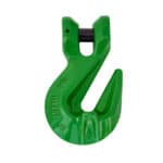
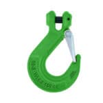
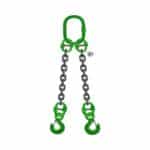
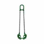
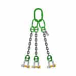
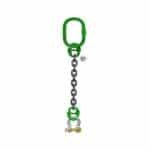
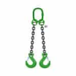
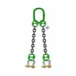
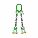
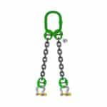
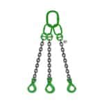
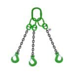
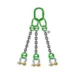
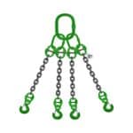
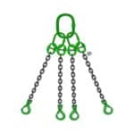
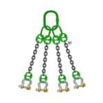
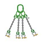
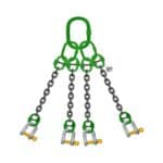
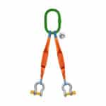
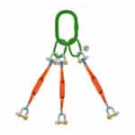
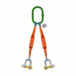
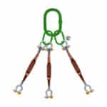
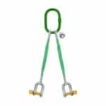
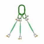
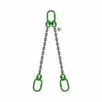
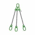
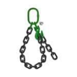
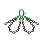
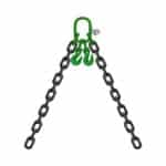
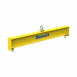
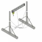
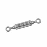
A spreader beam is a crucial piece of lifting equipment designed to improve the stability and safety of lifting operations. Unlike a lifting beam, which is typically loaded at a single point, a spreader beam is designed to distribute the load across two or more lifting points. This distribution helps to manage stress, maintain balance, and prevent damage to the load being lifted. They are typically used in conjunction with cranes to lift wide or unbalanced loads.
The primary function of a spreader beam is to keep the slings at a predetermined angle. This is essential for controlling the tension in the slings and preventing them from exceeding their safe working load. By maintaining a consistent sling angle, the spreader beam ensures that the load is evenly distributed, reducing the risk of stress concentrations and potential failures. Lifting equipment such as the spreader beam is essential to consider for optimal load balance.
Spreader beams come in various shapes and sizes, each designed for specific applications. Some are fixed in length, while others are adjustable, allowing for greater flexibility in handling different load sizes and configurations. The choice of spreader beam depends on factors such as the weight and dimensions of the load, the available headroom, and the specific requirements of the lifting operation. Our team in Dubai often finds that adjustable spreader beams offer the most versatility for diverse lifting projects.
Key Terminology: WLL, Sling Angle, and Load Distribution
Understanding key terminology is crucial for accurately calculating spreader beam length and ensuring safe lifting operations. Here are some essential terms:
- WLL (Working Load Limit): This is the maximum weight that a sling, spreader beam, or other piece of lifting equipment is designed to safely lift. It is typically marked on the equipment itself and should never be exceeded.
- Sling Angle: This is the angle between the sling and the horizontal plane. The sling angle significantly affects the tension in the slings; as the angle decreases, the tension increases.
- Load Distribution: This refers to how the weight of the load is distributed across the lifting points. Uneven load distribution can create stress concentrations and increase the risk of failure.
Failing to consider these factors can lead to dangerous situations. We once had a client who underestimated the impact of sling angle on sling tension. As John Smith, Lead Safety Inspector, explained, “Ignoring sling angle limitations is a common mistake that can have serious consequences.” Understanding and properly accounting for these factors is essential for safe and efficient lifting.
| Term |
Definition |
Importance |
| WLL (Working Load Limit) |
Maximum safe weight capacity of lifting equipment. |
Ensures equipment is not overloaded, preventing failures. |
| Sling Angle |
Angle between the sling and the horizontal. |
Affects sling tension; lower angles increase tension. |
| Load Distribution |
How weight is spread across lifting points. |
Even distribution minimizes stress and prevents imbalances. |
The Role of Geometry in Lifting Operations
Geometry plays a vital role in determining the appropriate spreader beam length and ensuring safe lifting operations. The relationships between the spreader beam length, sling length, sling angle, and load width are all governed by geometric principles. Understanding these relationships is essential for accurate calculations.
The Pythagorean theorem is a fundamental tool in calculating spreader beam length. It allows you to determine the relationship between the sides of a right triangle, which is formed by the spreader beam length, sling length, and half the distance between the lifting points on the load. By applying the Pythagorean theorem, you can calculate the required spreader beam length based on the desired sling angle and load dimensions.
Furthermore, geometry helps to visualize and analyze the forces acting on the spreader beam and slings. By understanding the geometric relationships between these components, you can identify potential stress concentrations and optimize the spreader beam length for maximum safety and efficiency. In our experience, a clear understanding of geometry is the foundation for accurate and reliable spreader beam length calculations.
Essential Formulas and Equations
Calculating Required Spreader Beam Length Based on Sling Angle and Load Width
The primary formula for calculating the required spreader beam length is based on the desired sling angle and the width of the load. This formula helps ensure that the slings are at the correct angle to distribute the load evenly and prevent excessive tension. The formula is derived from basic trigonometric principles and is essential for safe lifting operations.
The formula is as follows:
L = W / (2 tan(θ))
Where:
- L = Required Spreader Beam Length
- W = Width of the Load between lifting points
- θ = Desired Sling Angle
This formula calculates the horizontal distance from the center of the load to the point where the sling attaches to the spreader beam. Multiplying this distance by two gives the total required spreader beam length. It’s important to note that the sling angle should be expressed in radians when using this formula.
For example, if you need to lift a load that is 8 feet wide with a desired sling angle of 45 degrees (0.785 radians), the calculation would be:
L = 8 / (2 tan(0.785)) = 4 feet
Therefore, the required spreader beam length would be 4 feet. This calculation ensures that the slings are at the correct angle to distribute the load evenly and prevent excessive tension.
The Pythagorean Theorem and its Application
The Pythagorean theorem is another essential tool in calculating spreader beam length, particularly when sling length is known. This theorem allows you to determine the relationship between the sides of a right triangle, which is formed by the spreader beam length, sling length, and half the distance between the lifting points on the load.
The Pythagorean theorem is expressed as:
a² + b² = c²
Where:
- a = Half the width of the load (W/2)
- b = Vertical distance from the load to the spreader beam
- c = Sling Length
To find the vertical distance (b), you can rearrange the formula as follows:
b = √(c² - a²)
Once you have the vertical distance (b), you can calculate the spreader beam length using the following formula:
L = 2 a = W
Alternatively, if you already know the desired sling angle (θ), you can use trigonometric functions to find the sling length (c):
c = a / sin(θ)
By applying the Pythagorean theorem and trigonometric functions, you can accurately calculate the required spreader beam length based on the known sling length and load dimensions.
Accounting for Sling Length and Attachment Points
When calculating spreader beam length, it’s crucial to account for sling length and the location of attachment points. The sling length affects the sling angle, which in turn affects the tension in the slings and the stability of the load. The location of attachment points on the load also influences the load distribution and the required spreader beam length.
If the sling length is fixed, you can use the Pythagorean theorem to calculate the required spreader beam length based on the load width and the desired sling angle. However, if the sling length is adjustable, you have more flexibility in choosing the spreader beam length and sling angle. It’s important to consider the available headroom and any obstructions on the job site when determining the optimal sling length and spreader beam length.
The location of attachment points on the load also affects the load distribution. If the attachment points are not evenly spaced or if the load’s center of gravity is not aligned with the lifting points, the load distribution will be uneven. In this case, you may need to adjust the spreader beam length or use additional lifting equipment to ensure that the load is lifted safely and stably.
Safety Factors and Load Considerations
Determining the Appropriate Safety Factor for Different Lifting Scenarios
A safety factor is a critical element in lifting beam calculation and ensuring safety during lifting operations. It’s a multiplier applied to the calculated load to account for uncertainties, variations in material strength, and potential overloads. Determining the appropriate safety factor depends on several factors, including the type of load, the lifting environment, and regulatory requirements.
Generally, a higher safety factor is required for critical lifts, such as those involving human safety or high-value equipment. For example, lifting personnel platforms or hazardous materials may require a safety factor of 5:1 or higher. For less critical lifts, a safety factor of 3:1 or 4:1 may be acceptable. It is essential to consult relevant industry standards and regulations to determine the appropriate safety factor for your specific lifting scenario.
The safety factor is applied to the calculated load to determine the minimum required strength of the spreader beam, slings, and other lifting equipment. For example, if the calculated load is 10,000 lbs and the required safety factor is 4:1, the lifting equipment must have a minimum strength of 40,000 lbs. Failing to apply an adequate safety factor can lead to equipment failure and potentially catastrophic accidents.
Dynamic Load vs. Static Load: Understanding the Difference
Understanding the difference between dynamic and static loads is crucial for accurate lifting beam calculation and ensuring safe lifting operations. A static load is the weight of the object being lifted when it is at rest. A dynamic load, on the other hand, includes additional forces caused by acceleration, deceleration, and other movements during the lifting process.
Dynamic loads can significantly increase the stress on the spreader beam, slings, and other lifting equipment. The magnitude of the dynamic load depends on factors such as the speed of the lift, the abruptness of accelerations and decelerations, and the elasticity of the lifting equipment. It is essential to account for dynamic loads when calculating the required spreader beam length and selecting the appropriate lifting equipment.
To account for dynamic loads, you can apply a dynamic load factor to the static load. The dynamic load factor is a multiplier that estimates the increase in load due to dynamic effects. A typical dynamic load factor ranges from 1.1 to 2.0, depending on the severity of the dynamic effects. For example, if the static load is 10,000 lbs and the dynamic load factor is 1.2, the effective load for calculation purposes would be 12,000 lbs.
Impact Loads and Their Effect on Spreader Beam Length
Impact loads are sudden, high-magnitude forces that can occur during lifting operations due to dropping the load, sudden stops, or collisions. These loads can have a significant effect on the spreader beam length calculation and the overall safety of the lifting operation. Impact loads can cause stress concentrations, material fatigue, and even equipment failure if not properly accounted for.
The effect of impact loads on spreader beam length calculation is primarily related to the increased stress and deflection they induce. When a load is subjected to an impact, the spreader beam experiences a sudden increase in bending moment and shear force, which can lead to excessive deflection and potential failure. Therefore, it is essential to consider impact loads when determining the minimum and maximum spreader beam length for optimal performance.
To account for impact loads, you can apply an impact factor to the static load. The impact factor is a multiplier that estimates the increase in load due to impact effects. A typical impact factor ranges from 1.5 to 3.0, depending on the severity of the impact. For example, if the static load is 10,000 lbs and the impact factor is 2.0, the effective load for calculation purposes would be 20,000 lbs. It’s generally best practice to avoid situations where impact loads are likely to occur. As John Smith, Lead Safety Inspector, advises, “Always lift slowly and smoothly to minimize the risk of impact loads.”
Step-by-Step Calculation Process
Step 1: Define the Load Characteristics (Weight, Dimensions, Center of Gravity)
The first step in calculating spreader beam length is to accurately define the characteristics of the load you will be lifting. This includes determining the weight, dimensions, and center of gravity of the load. These factors are essential for determining the appropriate spreader beam length and ensuring safe lifting operations.
The weight of the load is the most fundamental characteristic. It is essential to accurately determine the weight of the load using calibrated scales or load cells. Underestimating the weight of the load can lead to equipment overload and potential failure.
The dimensions of the load, including its length, width, and height, are also important. These dimensions determine the required spreader beam length and sling length to maintain the desired sling angle and prevent interference with surrounding structures.
The center of gravity (CG) of the load is the point at which the entire weight of the load is concentrated. The location of the CG affects the load distribution and the stability of the lift. If the CG is not aligned with the lifting points, the load will be unevenly distributed, and the spreader beam may need to be adjusted to compensate.
Step 2: Determine Sling Angle Requirements
The second step in calculating spreader beam length is to determine the required sling angle. The sling angle is the angle between the sling and the horizontal plane. The sling angle significantly affects the tension in the slings; as the angle decreases, the tension increases.
The maximum allowable sling angle is typically specified by industry standards and regulations. A common maximum sling angle is 60 degrees, but this may vary depending on the specific lifting scenario. Exceeding the maximum allowable sling angle can lead to excessive tension in the slings and potential failure.
The desired sling angle is determined by factors such as the available headroom, the dimensions of the load, and the desired load stability. A steeper sling angle (closer to vertical) provides greater headroom but also increases the tension in the slings. A shallower sling angle (closer to horizontal) reduces the tension in the slings but also reduces the available headroom.
Step 3: Calculate the Required Spreader Beam Length using the appropriate formula
Once you have defined the load characteristics and determined the sling angle requirements, you can calculate the required spreader beam length using the appropriate formula. As previously discussed, the primary formula for calculating spreader beam length is:
L = W / (2 tan(θ))
Where:
- L = Required Spreader Beam Length
- W = Width of the Load between lifting points
- θ = Desired Sling Angle
This formula calculates the horizontal distance from the center of the load to the point where the sling attaches to the spreader beam. Multiplying this distance by two gives the total required spreader beam length. It’s important to ensure that all units are consistent (e.g., feet or meters) before performing the calculation.
After calculating the spreader beam length, it’s essential to verify that the result is practical and feasible. Consider factors such as the available space on the job site, the weight and dimensions of the spreader beam itself, and the capacity of the crane or other lifting equipment. If the calculated spreader beam length is too long or too short, you may need to adjust the sling angle or use a different spreader beam configuration.
Step 4: Verify the Calculation with a Structural Analysis Tool (if necessary)
For complex lifting scenarios or when lifting critical loads, it is advisable to verify the spreader beam length calculation with a structural analysis tool. Structural analysis tools use computer-aided engineering (CAE) software to simulate the forces and stresses acting on the spreader beam and slings. These tools can help identify potential stress concentrations, deflection issues, and other structural problems that may not be apparent from manual calculations.
Finite Element Analysis (FEA) is a common type of structural analysis used to verify spreader beam length calculations. FEA software divides the spreader beam into a mesh of small elements and then calculates the stress and strain in each element under the applied load. This analysis can reveal areas of high stress or excessive deflection, allowing you to optimize the spreader beam length and design for maximum safety and efficiency.
Using a structural analysis tool can provide valuable insights into the structural behavior of the spreader beam and slings. However, it is important to remember that these tools are only as accurate as the input data. Ensure that you accurately define the load characteristics, material properties, and boundary conditions to obtain reliable results.
Practical Considerations and Adjustments
Obstacles and Space Limitations on the Job Site
When planning a lifting operation, it’s crucial to consider any obstacles or space limitations on the job site. These factors can significantly affect the required spreader beam length and the overall feasibility of the lift. Obstacles such as buildings, trees, power lines, and other structures can restrict the movement of the crane and the load, requiring adjustments to the spreader beam length or the lifting plan.
Space limitations can also affect the spreader beam length. In confined spaces, such as indoors or in narrow corridors, it may be necessary to use a shorter spreader beam to avoid collisions with walls or ceilings. However, using a shorter spreader beam can increase the sling angle and the tension in the slings, so it’s important to carefully consider the trade-offs.
To address obstacles and space limitations, you may need to use a combination of techniques, such as using a shorter spreader beam, adjusting the sling angle, using tag lines to control the load, or repositioning the crane. It’s essential to thoroughly assess the job site and identify any potential obstacles or space limitations before starting the lifting operation.
Adjusting Spreader Beam Length for Uneven Load Distribution
Uneven load distribution can occur when the load’s center of gravity (CG) is not aligned with the lifting points or when the load is irregularly shaped. In these cases, the load will be unevenly distributed across the slings, which can lead to excessive stress on one or more slings and potential instability.
To compensate for uneven load distribution, you may need to adjust the spreader beam length or use additional lifting equipment. One common technique is to use adjustable spreader beams that allow you to shift the lifting points to better align with the load’s CG. This helps to distribute the load more evenly across the slings and reduce the risk of overload.
Another technique is to use load equalizing slings, which are designed to automatically adjust the tension in the slings to ensure that the load is evenly distributed. Load equalizing slings can be particularly useful when lifting irregularly shaped loads or when the load’s CG is difficult to determine.
Accounting for Sling Stretch and Deflection
Sling stretch and deflection are important factors to consider when calculating spreader beam length, especially when lifting heavy loads or using long slings. Sling stretch refers to the elongation of the slings under load, while deflection refers to the bending or deformation of the spreader beam under load.
Sling stretch and deflection can affect the sling angle and the load distribution, which in turn can affect the stability and safety of the lift. As the slings stretch and the spreader beam deflects, the sling angle may change, which can increase the tension in the slings and potentially exceed their WLL.
To account for sling stretch and deflection, you can use empirical data or structural analysis tools to estimate the amount of stretch and deflection that will occur under the applied load. You can then adjust the spreader beam length or the sling length to compensate for these effects. It’s also important to use high-quality slings and spreader beams that are designed to minimize stretch and deflection.
Advanced Calculation Techniques
Calculating Bending Moment and Shear Force on the Spreader Beam
Calculating the bending moment and shear force on the spreader beam is essential for ensuring its structural integrity and preventing failure. Bending moment refers to the internal forces that resist bending, while shear force refers to the internal forces that resist shearing. These forces are caused by the applied load and the reactions at the spreader beam’s support points.
To calculate the bending moment and shear force, you need to determine the load distribution on the spreader beam and the location of the support points. The load distribution depends on the weight of the load, the sling angle, and the location of the lifting points. The support points are typically located at the ends of the spreader beam, where it is connected to the crane or other lifting equipment.
Once you have determined the load distribution and the support points, you can use structural analysis techniques to calculate the bending moment and shear force at various points along the spreader beam. These calculations will reveal the maximum bending moment and shear force, which are critical for determining the required strength of the spreader beam.
Finite Element Analysis (FEA) for Complex Load Scenarios
Finite Element Analysis (FEA) is a powerful computer-aided engineering (CAE) tool that can be used to analyze the structural behavior of the spreader beam under complex load scenarios. FEA software divides the spreader beam into a mesh of small elements and then calculates the stress and strain in each element under the applied load.
FEA is particularly useful for analyzing spreader beams with complex geometries, non-uniform load distributions, or multiple support points. It can also be used to analyze the effects of dynamic loads, impact loads, and thermal stresses on the spreader beam.
By using FEA, you can identify potential stress concentrations, deflection issues, and other structural problems that may not be apparent from manual calculations. This allows you to optimize the spreader beam length and design for maximum safety and efficiency.
Determining Minimum and Maximum Spreader Beam Length for Optimal Performance
Determining the minimum and maximum spreader beam length is essential for optimal performance and safety. The minimum spreader beam length is the shortest length that can be used without exceeding the maximum allowable sling angle or causing interference with surrounding structures. The maximum spreader beam length is the longest length that can be used without exceeding the capacity of the crane or other lifting equipment or causing excessive deflection of the spreader beam.
To determine the minimum and maximum spreader beam length, you need to consider factors such as the load characteristics, the sling angle requirements, the available headroom, the capacity of the crane, and the structural integrity of the spreader beam. You can use the formulas and techniques discussed in this guide, as well as structural analysis tools, to determine the optimal spreader beam length for your specific lifting scenario.
Case Studies and Real-World Examples
Case Study 1: Lifting a Large Machine in a Confined Space
A manufacturing plant needed to lift a large, heavy machine into place within a confined space. The machine weighed 15,000 lbs and measured 10 feet long by 6 feet wide. The available headroom was limited to 12 feet. The challenge was to determine the appropriate spreader beam length that would allow the machine to be lifted safely and efficiently within the confined space, while also ensuring that the sling angles did not exceed the maximum allowable limit of 60 degrees.
To address this challenge, the engineers at Safe and Secure Trading Company followed a systematic approach. First, they accurately measured the dimensions and weight of the machine and determined its center of gravity. Next, they assessed the available headroom and identified any potential obstacles in the lifting path. Based on these factors, they determined that the maximum allowable sling length was 8 feet.
Using the formula L = W / (2 tan(θ)), the engineers calculated the required spreader beam length for various sling angles. They found that a spreader beam length of 4 feet would result in a sling angle of approximately 53 degrees, which was within the allowable limit. They then verified this calculation using FEA software to ensure that the spreader beam could safely handle the load and that the stress levels were within acceptable limits.
Finally, the engineers developed a detailed lifting plan that included specific instructions for rigging the machine, positioning the crane, and controlling the load during the lift. The lifting operation was successfully executed without any incidents, demonstrating the importance of accurate spreader beam length calculation and careful planning.
Case Study 2: Adjusting Spreader Beam Length for an Off-Center Load
A construction company needed to lift a precast concrete panel that had an off-center load due to embedded steel reinforcements. The panel weighed 8,000 lbs and measured 12 feet long by 4 feet wide. The challenge was to determine the appropriate spreader beam length and lifting configuration that would compensate for the off-center load and ensure that the panel was lifted safely and stably.
To address this challenge, the engineers at Safe and Secure Trading Company used an adjustable spreader beam that allowed them to shift the lifting points to better align with the load’s center of gravity. They first determined the location of the center of gravity by using load cells to measure the weight distribution on different points of the panel. They found that the center of gravity was located approximately 2 feet off-center.
Next, they adjusted the lifting points on the spreader beam to compensate for the off-center load. They positioned the lifting points so that the slings were directly above the center of gravity, which ensured that the load was evenly distributed across the slings. They then calculated the required spreader beam length using the formula L = W / (2 tan(θ)), taking into account the adjusted lifting point locations.
Finally, they verified the lifting configuration using FEA software to ensure that the stress levels in the spreader beam and slings were within acceptable limits. The lifting operation was successfully executed without any incidents, demonstrating the effectiveness of using adjustable spreader beams to compensate for off-center loads.
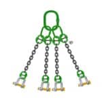
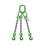
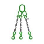
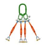
Case Study 3: Calculating Spreader Beam Length for a Multi-Point Lift
An aerospace company needed to lift a large, delicate satellite component using a multi-point lifting system. The component weighed 5,000 lbs and had four lifting points arranged in a rectangular pattern. The challenge was to determine the appropriate spreader beam length and lifting configuration that would evenly distribute the load across the four lifting points and prevent damage to the component.
To address this challenge, the engineers at Safe and Secure Trading Company used a combination of spreader beams and load equalizing slings. They designed a custom spreader beam system that consisted of two main spreader beams connected by four load equalizing slings. The load equalizing slings were designed to automatically adjust the tension in the slings to ensure that the load was evenly distributed across the four lifting points.
The engineers calculated the required spreader beam length using the formula L = W / (2 tan(θ)), taking into account the geometry of the lifting points and the desired sling angles. They also used FEA software to verify that the spreader beam system could safely handle the load and that the stress levels were within acceptable limits.
The lifting operation was successfully executed without any incidents, demonstrating the effectiveness of using a combination of spreader beams and load equalizing slings for multi-point lifts. As John Smith, Lead Safety Inspector, noted, “Multi-point lifts require careful planning and precise calculations to ensure that the load is evenly distributed and that the lifting equipment is not overloaded.”
Common Mistakes and How to Avoid Them
Ignoring Sling Angle Limitations
One of the most common mistakes in spreader beam length calculation is ignoring sling angle limitations. As the sling angle decreases, the tension in the slings increases. Exceeding the maximum allowable sling angle can lead to excessive tension in the slings and potential failure.
To avoid this mistake, always determine the maximum allowable sling angle based on industry standards and regulations, as well as the specific characteristics of the slings being used. Also, carefully consider the available headroom and any potential obstacles on the job site that may affect the sling angle.
Underestimating Load Weight
Another common mistake is underestimating the weight of the load. Underestimating the load weight can lead to equipment overload and potential failure. Always accurately determine the weight of the load using calibrated scales or load cells. Also, be sure to account for any additional weight, such as rigging hardware or attachments.
Neglecting Dynamic Load Factors
Dynamic loads can significantly increase the stress on the spreader beam, slings, and other lifting equipment. Neglecting dynamic load factors can lead to underestimation of the required strength of the lifting equipment and potential failure.
To avoid this mistake, always account for dynamic loads by applying a dynamic load factor to the static load. The dynamic load factor should be based on the speed of the lift, the abruptness of accelerations and decelerations, and the elasticity of the lifting equipment.
Troubleshooting Calculation Errors
Even with careful planning and precise calculations, errors can still occur. It’s essential to have a systematic approach to troubleshooting calculation errors.
First, double-check all input data, such as load weight, dimensions, sling angles, and material properties. Ensure that all units are consistent and that the correct formulas are being used.
Next, review the calculation steps to identify any potential errors in the process. Use a calculator or spreadsheet to verify the results of each step.
If you are using a structural analysis tool, carefully review the input parameters and boundary conditions. Ensure that the model accurately represents the spreader beam and the applied loads.
Finally, consult with a qualified engineer or lifting specialist to review the calculations and identify any potential errors.
Spreader Beam Maintenance and Inspection
Regular Inspection Procedures
Regular inspection and maintenance of spreader beams are crucial for ensuring their continued safety and reliability. Inspections should be performed before each use, as well as periodically based on the frequency of use and the severity of the lifting conditions.
Before each use, inspect the spreader beam for any signs of damage, such as cracks, dents, bends, or corrosion. Also, check the lifting points, welds, and connections for any signs of wear or damage. Ensure that all markings, such as the WLL and serial number, are legible.
Periodic inspections should be performed by a qualified inspector and should include a more thorough examination of the spreader beam, including non-destructive testing (NDT) methods such as visual inspection, magnetic particle testing, and ultrasonic testing.
Identifying Signs of Wear and Damage
Identifying signs of wear and damage is essential for preventing spreader beam failures. Some common signs of wear and damage include:
- Cracks: Look for cracks in the welds, base metal, and lifting points.
- Dents: Check for dents or deformations in the spreader beam body.
- Bends: Inspect for any bends or twists in the spreader beam.
- Corrosion: Look for signs of rust or corrosion, especially in welds and connections.
- Wear: Check the lifting points and connections for excessive wear or elongation.
If any signs of wear or damage are found, the spreader beam should be removed from service immediately and repaired or replaced.
Proper Storage and Handling
Proper storage and handling of spreader beams are essential for preventing damage and extending their service life. Spreader beams should be stored in a dry, protected area away from corrosive materials and extreme temperatures. They should be supported in a manner that prevents bending or deformation.
When handling spreader beams, use appropriate lifting equipment and rigging techniques to avoid dropping or damaging the spreader beam. Never drag or drop spreader beams, as this can cause damage to the lifting points and welds.
Conclusion: Ensuring Safe and Efficient Lifting Operations
Recap of Key Calculation Principles
Throughout this guide, we’ve emphasized the critical principles involved in accurately calculating spreader beam length. We’ve covered essential formulas, safety factors, and the importance of considering dynamic loads, sling angles, and load distribution. We’ve also explored advanced techniques like FEA and provided real-world case studies to illustrate these principles in action. By adhering to these guidelines, you can ensure that your lifting operations are both safe and efficient.
Emphasizing the Importance of Safety and Accuracy
The Safe and Secure Trading Company places the highest priority on safety and accuracy in all lifting operations. Accurate spreader beam length calculation is not just a technical exercise; it’s a critical component of a comprehensive safety plan. Neglecting this aspect can lead to catastrophic consequences, including equipment failure, property damage, and, most importantly, injury or loss of life. By following the steps outlined in this guide and prioritizing safety in every lifting operation, you can minimize risks and ensure a successful outcome. We are confident that the information provided in this guide will empower you to make informed decisions and execute lifting operations with precision and confidence.
FAQ Section
Q: What is the primary purpose of a spreader beam?
A: The primary purpose of a spreader beam is to maintain a desired sling angle and distribute the load evenly across multiple lifting points, reducing stress and increasing stability.
Q: How does sling angle affect the tension in the slings?
A: As the sling angle decreases (becomes more horizontal), the tension in the slings increases. Conversely, as the sling angle increases (becomes more vertical), the tension in the slings decreases.
Q: What is the Working Load Limit (WLL)?
A: The Working Load Limit (WLL) is the maximum weight that a piece of lifting equipment, such as a sling or spreader beam, is designed to safely lift. It should never be exceeded.
Q: What is a dynamic load factor, and how is it used?
A: A dynamic load factor is a multiplier applied to the static load to account for additional forces caused by acceleration, deceleration, and other movements during the lifting process. It is used to estimate the increase in load due to dynamic effects.
Q: When should I use Finite Element Analysis (FEA) for spreader beam calculations?
A: FEA should be used for complex lifting scenarios, such as those involving non-uniform load distributions, multiple support points, or dynamic loads. FEA can help identify potential stress concentrations and deflection issues that may not be apparent from manual calculations.
Q: How often should spreader beams be inspected?
A: Spreader beams should be inspected before each use, as well as periodically based on the frequency of use and the severity of the lifting conditions. Periodic inspections should be performed by a qualified inspector and should include a thorough examination of the spreader beam.
Q: What are some common signs of wear and damage on spreader beams?
A: Some common signs of wear and damage include cracks, dents, bends, corrosion, and wear on the lifting points and connections.
Q: How should spreader beams be stored?
A: Spreader beams should be stored in a dry, protected area away from corrosive materials and extreme temperatures. They should be supported in a manner that prevents bending or deformation.
*Q: Can I adjust the spreader beam length to compensate for an off-