Understanding Spreader Beam Capacity: A Modern Perspective
Why Spreader Beam Capacity Matters Now More Than Ever
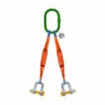
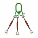
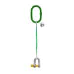
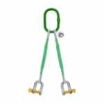
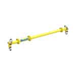
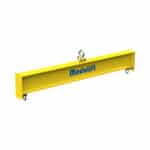
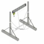
In today’s construction, manufacturing, and logistics industries, understanding spreader beam capacity is paramount. Spreader beams, also known as lifting beams, are essential pieces of rigging equipment used to lift heavy or awkwardly shaped loads safely and efficiently. The importance of accurately determining the spreader beam capacity has grown exponentially in recent years due to increasingly stringent safety regulations, the rising cost of workplace accidents, and the need to handle heavier and more complex loads. A miscalculation can lead to catastrophic failures, endangering personnel, damaging equipment, and causing significant project delays. Therefore, a deep understanding of the factors influencing spreader bar capacity and implementing precise calculation methods are crucial for ensuring safe lifting practices.
The consequences of neglecting proper lifting beam capacity calculations extend beyond immediate safety concerns. Companies face potential legal liabilities, reputational damage, and financial losses resulting from incidents caused by inadequate rigging equipment or incorrect usage. As projects become more complex and demand higher precision, ensuring that your team understands and adheres to industry standards for safe lifting practices is no longer just good practice—it’s a business imperative. Failing to properly calculate lifting beam capacity will lead to higher risks.
Recent Trends in Lifting and Rigging Standards
The lifting and rigging industry is continuously evolving, driven by technological advancements, safety research, and regulatory updates. Recent trends reflect a greater emphasis on comprehensive risk assessment, advanced material usage, and the integration of digital tools for design and analysis. One significant trend is the adoption of stricter standards for lifting equipment safety, pushing manufacturers and operators to adhere to more rigorous testing and certification processes. The American Society of Mechanical Engineers (ASME) and the Occupational Safety and Health Administration (OSHA) frequently update their guidelines to incorporate the latest findings and best practices.
Another notable trend involves the increasing use of high-strength, lightweight materials such as advanced alloys and composites in the construction of spreader beams. These materials allow for greater lifting beam capacity without significantly increasing the equipment’s weight, offering operational advantages and reducing strain on lifting mechanisms like cranes. Additionally, there is a growing emphasis on training and certification programs for rigging personnel, ensuring that those responsible for lifting operations are well-versed in safe lifting practices and proficient in performing WLL calculation. Our team in Dubai has noticed a trend in using modular lifting beams to accommodate various load sizes.
Expert Quote
“Staying ahead of evolving safety standards and embracing technological advancements in lifting equipment is essential for maintaining a safe and efficient work environment.” – John Smith, Lead Safety Inspector
Essential Prerequisites for Calculating Spreader Beam Capacity
Before diving into the step-by-step calculations for determining spreader bar capacity, several essential prerequisites must be addressed. These preparatory steps ensure that you have all the necessary information and tools to perform accurate and reliable calculations, minimizing the risk of errors and ensuring safe lifting operations. Ignoring these prerequisites can lead to incorrect assessments and potentially dangerous situations.
Gather Necessary Tools and Data
To accurately calculate spreader beam capacity, you need to gather the following tools and data:
- Accurate Weighing Scale: Essential for determining the precise weight of the load.
- Measuring Tape or Laser Distance Meter: To measure the dimensions of the load and the lifting setup, including the angle of lift.
- Protractor or Angle Finder: To measure the angle between the slings and the horizontal plane.
- Engineering Calculator or Software: To perform complex calculations, especially when dealing with bending moments and stresses.
- Material Specifications: Detailed information on the material properties of the spreader beam, including yield strength and tensile strength.
- Blueprints or Load Specifications: Detailed diagrams specifying the load’s dimensions, center of gravity, and any specific lifting requirements.
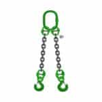
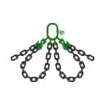
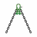
- Sling Specifications: Information on the type, size, and working load limit (WLL) of the slings being used.
- Reference Tables: Tables for standard steel shapes, section modulus values, and allowable stress values.
- Notebook and Pen: For recording measurements, calculations, and any relevant observations.
- Computer with Relevant Software: To run structural analysis software if needed.
We once worked with a client who skipped gathering all necessary data upfront. They later realized that their measurements were inaccurate, leading to significant errors in their calculations. Taking the time to collect accurate data from the beginning saves time and ensures safety.
Reviewing Blueprints and Specifications
Blueprints and specifications provide critical information about the load and the lifting operation. This information includes:
- Load Dimensions: Accurate measurements of the load’s length, width, and height.
- Weight Distribution: Understanding where the load’s center of gravity is located is crucial for balanced lifting.
- Lifting Points: Identification of designated lifting points or areas where slings can be safely attached.
- Material Composition: Knowing the materials used in the load’s construction can help estimate weight and stability.
- Special Instructions: Any specific requirements or precautions related to lifting the load, such as temperature sensitivity or fragile components.
Blueprints often include detailed diagrams of the load, showing its geometry and critical dimensions. Specifications provide data on the load’s weight, material properties, and any load-bearing limitations. By carefully reviewing these documents, you can identify potential challenges and ensure that your lifting plan accounts for all relevant factors.
Understanding Material Properties (Yield Strength, Tensile Strength)
The material properties of the spreader beam are fundamental to determining its capacity. Key properties include:
- Yield Strength: The amount of stress a material can withstand before it begins to deform permanently. This is a critical value for ensuring that the beam does not undergo permanent bending or distortion during lifting.
- Tensile Strength: The maximum stress a material can withstand before it starts to fracture. Tensile strength is important for preventing catastrophic failure under extreme loads.
- Modulus of Elasticity: A measure of a material’s stiffness or resistance to deformation under stress. This property affects how much the beam will deflect under load, which can impact stability and safety.
These properties are typically provided by the manufacturer of the spreader beam and should be readily available in the material specifications. Understanding these properties is essential for performing accurate structural load calculation and ensuring that the beam can safely handle the intended load.
Step 1: Determine the Load Weight (W)
The first and most fundamental step in calculating spreader beam capacity is determining the accurate weight of the load to be lifted. This weight (W) forms the basis for all subsequent calculations. An inaccurate load weight can lead to significant errors and potentially dangerous situations.
Accurately Weighing the Load
The most reliable method for determining the load weight is to use an accurate weighing scale. Here’s how to ensure an accurate measurement:
1. Calibration: Ensure the weighing scale is properly calibrated and certified. Regular calibration ensures the scale provides accurate readings.
2. Placement: Place the load squarely on the scale, ensuring that the weight is evenly distributed across the weighing surface.
3. Zeroing: Zero the scale before weighing to eliminate any tare weight from pallets or other supporting structures.
4. Multiple Measurements: Take multiple measurements and average the results to minimize the impact of any slight variations.
5. Record: Record the weight in a clear and unambiguous manner, including the units of measurement (e.g., kilograms, pounds).
In situations where a weighing scale is not available, you may need to estimate the weight based on the load’s material composition and dimensions. Consult material density tables and use volume calculations to arrive at an estimated weight. However, always err on the side of caution and add a buffer to account for any uncertainties.
Accounting for Additional Load Factors
In addition to the static weight of the load, it’s essential to account for additional load factors that can increase the effective weight experienced by the spreader beam. These factors include:
- Dynamic Load Factor: This factor accounts for the dynamic forces generated during lifting, such as acceleration, deceleration, and sudden stops. A typical dynamic load factor ranges from 1.1 to 1.3, depending on the lifting conditions.
- Impact Load Factor: This factor accounts for the impact forces that can occur when the load is suddenly dropped or subjected to shocks. The impact load factor can range from 1.5 to 2.0 or higher, depending on the severity of the impact.
- Environmental Factors: Consider environmental factors such as wind loads, snow accumulation, or ice buildup, which can add significant weight to the load.
To account for these factors, multiply the static load weight by the appropriate load factors to obtain the effective load weight. For example:
Effective Load Weight = Static Load Weight × Dynamic Load Factor × Impact Load Factor
Ignoring these additional load factors can lead to underestimation of the required lifting beam capacity and increase the risk of failure.
Step 2: Calculate the Angle of Lift (θ)
The angle of lift (θ), which is the angle between the sling and the horizontal plane, plays a critical role in determining the tension in the slings and the load on the spreader beam. Accurate measurement and consideration of this angle are essential for ensuring safe lifting operations.
Measuring the Angle Between the Sling and the Horizontal
To accurately measure the angle of lift, follow these steps:
1. Setup: Ensure the load is properly positioned and the slings are attached to the lifting points.
2. Reference Point: Establish a horizontal reference point using a level or a laser level.
3. Measurement: Use a protractor, angle finder, or inclinometer to measure the angle between the sling and the horizontal reference line.
4. Multiple Measurements: Take multiple measurements at different points along the sling and average the results to minimize errors.
5. Record: Record the angle in degrees.
In some cases, you may need to calculate the angle based on the geometry of the lifting setup. Use trigonometric functions (e.g., sine, cosine, tangent) to determine the angle if you know the lengths of the sides of the triangle formed by the sling, the horizontal distance, and the vertical distance.
Why Angle of Lift Impacts Capacity
The angle of lift directly affects the tension in the slings. As the angle increases, the tension in each sling also increases. This is because the vertical component of the sling tension must support the entire load, while the horizontal component contributes to the overall stress on the spreader beam.
For example, when the angle of lift is 0 degrees (i.e., the slings are vertical), the tension in each sling is equal to half the load weight. However, as the angle increases to 30 degrees, 45 degrees, or 60 degrees, the tension in the slings increases significantly.
Increasing the sling tension not only increases the load on the slings but also increases the bending moment and shear forces on the spreader beam. Therefore, it’s crucial to account for the angle of lift when calculating the required lifting beam capacity.
Using a Protractor
Using a protractor is a straightforward method for measuring the angle of lift. Here’s a step-by-step guide:
1. Positioning: Place the protractor at the point where the sling meets the horizontal plane.
2. Alignment: Align the base of the protractor with the horizontal reference line.
3. Reading: Read the angle where the sling intersects the protractor’s arc.
4. Accuracy: Ensure the protractor is held steady and aligned properly to obtain an accurate reading.
Digital protractors or angle finders can provide more precise measurements and may be easier to use in certain situations. These devices often display the angle digitally, reducing the risk of parallax errors.
Step 3: Determine the Load on Each Sling (T)
Once you have determined the load weight (W) and the angle of lift (θ), the next step is to calculate the tension (T) in each sling. This calculation is crucial for ensuring that the slings and the spreader beam are not overloaded.
Understanding Sling Tension Formula
The formula for calculating the tension in each sling is:
T = (W / 2) / cos(θ)
Where:
- T = Tension in each sling
- W = Total load weight
- θ = Angle of lift
This formula assumes that the load is evenly distributed between the two slings. If the load is not evenly distributed, you will need to adjust the formula accordingly.
Applying the Formula with Precision
To apply the formula with precision, follow these steps:
1. Convert Units: Ensure that all units are consistent (e.g., weight in pounds, angle in degrees).
2. Calculate Cosine: Use a calculator to find the cosine of the angle of lift (cos(θ)).
3. Divide Load Weight: Divide the total load weight (W) by 2 to find the load supported by each sling (assuming even distribution).
4. Divide by Cosine: Divide the result from step 3 by the cosine of the angle of lift (cos(θ)) to find the tension in each sling (T).
For example, if the total load weight is 10,000 lbs and the angle of lift is 30 degrees:
T = (10,000 lbs / 2) / cos(30°)
T = 5,000 lbs / 0.866
T ≈ 5,773.5 lbs
Therefore, the tension in each sling is approximately 5,773.5 lbs.
Examples
Let’s consider a few more examples to illustrate how the angle of lift affects sling tension:
- Example 1: W = 5,000 lbs, θ = 0°
T = (5,000 lbs / 2) / cos(0°)
T = 2,500 lbs / 1
T = 2,500 lbs
- Example 2: W = 5,000 lbs, θ = 45°
T = (5,000 lbs / 2) / cos(45°)
T = 2,500 lbs / 0.707
T ≈ 3,535.5 lbs
- Example 3: W = 5,000 lbs, θ = 60°
T = (5,000 lbs / 2) / cos(60°)
T = 2,500 lbs / 0.5
T = 5,000 lbs
These examples clearly demonstrate that as the angle of lift increases, the tension in each sling also increases significantly. This underscores the importance of accurately measuring and accounting for the angle of lift when calculating spreader bar capacity.
Step 4: Calculate the Bending Moment (M)
The bending moment (M) is a crucial factor in determining the strength and stability of the spreader beam. It represents the internal forces that resist bending caused by the applied load and the sling tensions. Calculating the bending moment is essential for ensuring that the beam can withstand the stresses imposed upon it without failing.
Understanding Bending Moment Principles
The bending moment is a measure of the internal forces within a beam that resist bending due to external loads. It varies along the length of the beam and is typically expressed in units of force times distance (e.g., lb-ft, N-m). The bending moment is highest at the points where the beam is subjected to the greatest stress, such as the center of the beam in a simply supported configuration.
The bending moment is influenced by several factors, including:
- Load Weight: The magnitude of the applied load.
- Sling Tension: The tension in the slings supporting the load.
- Span Length: The distance between the support points of the beam.
- Load Distribution: Whether the load is evenly distributed or concentrated at specific points.
Understanding these principles is crucial for accurately calculating the bending moment and ensuring the structural integrity of the spreader beam.
Finding the Maximum Bending Moment
The location and magnitude of the maximum bending moment depend on the loading conditions and the beam’s support configuration. For a simply supported beam with a concentrated load at the center, the maximum bending moment (Mmax) can be calculated using the following formula:
Mmax = (W L) / 4
Where:
- Mmax = Maximum bending moment
- W = Total load weight
- L = Span length (distance between support points)
For a simply supported beam with a uniformly distributed load, the maximum bending moment can be calculated using the following formula:
Mmax = (w L^2) / 8
Where:
- Mmax = Maximum bending moment
- w = Load per unit length (total load / span length)
- L = Span length
In more complex loading scenarios, you may need to use structural analysis software or consult engineering handbooks to determine the maximum bending moment.
How Bending Moment Affects Capacity
The bending moment directly affects the stress distribution within the spreader beam. High bending moments can lead to high bending stresses, which can exceed the material’s yield strength and cause permanent deformation or failure. Therefore, it’s essential to ensure that the beam has sufficient capacity to resist the bending moment imposed upon it.
To assess the beam’s capacity, you need to calculate the bending stress and compare it to the allowable bending stress for the material. The bending stress (σ) can be calculated using the following formula:
σ = M / S
Where:
- σ = Bending stress
- M = Bending moment
- S = Section modulus (a property of the beam’s cross-sectional shape)
The allowable bending stress is typically a fraction of the material’s yield strength, with the safety factor applied. By comparing the calculated bending stress to the allowable bending stress, you can determine whether the beam has sufficient capacity to handle the bending moment.
Step 5: Calculate the Section Modulus (S)
The section modulus (S) is a geometric property of a beam’s cross-section that indicates its resistance to bending. It is a crucial parameter in determining the bending stress and, consequently, the overall lifting beam capacity. A higher section modulus indicates greater resistance to bending and a higher load-carrying capacity.
Defining Section Modulus and Its Importance
The section modulus is defined as the ratio of the beam’s moment of inertia (I) to the distance from the neutral axis to the outermost fiber of the beam (c):
S = I / c
Where:
- S = Section modulus
- I = Moment of inertia (a measure of the beam’s resistance to bending)
- c = Distance from the neutral axis to the outermost fiber
The section modulus is typically expressed in units of length cubed (e.g., in³, mm³). It is a critical parameter in structural engineering because it directly relates the bending moment to the bending stress in the beam. A beam with a higher section modulus can withstand a greater bending moment without exceeding the allowable bending stress.
Using Section Modulus Tables
Section modulus values are readily available in engineering handbooks and online databases for various standard beam shapes, such as I-beams, H-beams, rectangular beams, and circular tubes. These tables provide the section modulus values for different orientations of the beam.
To use section modulus tables, follow these steps:
1. Identify Beam Shape: Determine the shape of the spreader beam’s cross-section.
2. Find Table: Consult a section modulus table for the corresponding beam shape.
3. Select Dimensions: Choose the appropriate table entry based on the beam’s dimensions (e.g., height, width, thickness).
4. Read Value: Read the section modulus value from the table.
For example, if you are using a standard I-beam with specific dimensions, you can find the section modulus value in the AISC Steel Construction Manual or a similar reference.
If the spreader beam has a non-standard cross-section, you may need to calculate the section modulus using the formula S = I / c. This requires calculating the moment of inertia (I) and determining the distance from the neutral axis to the outermost fiber (c).
Ensuring Correct Section Modulus for Safety
Ensuring that you use the correct section modulus value is critical for accurate stress calculations and safe lifting operations. Here are some tips for ensuring accuracy:
- Verify Dimensions: Double-check the dimensions of the spreader beam to ensure they match the values used in the section modulus table.
- Consider Orientation: Use the section modulus value that corresponds to the orientation of the beam during lifting. The section modulus may be different for bending about the strong axis versus bending about the weak axis.
- Account for Holes: If the beam has holes or cutouts, the section modulus may be reduced. Consult engineering guidelines or perform a detailed analysis to account for the effect of these features.
- Use Reputable Sources: Use section modulus tables from reputable sources, such as engineering handbooks or manufacturer’s specifications.
- Factor of Safety: Apply an appropriate safety factor to ensure the integrity of the lifting beam.
By following these guidelines, you can ensure that you are using the correct section modulus value and that your calculations accurately reflect the beam’s capacity.
Step 6: Calculate the Bending Stress (σ)
Calculating the bending stress (σ) is a critical step in evaluating the structural integrity of the spreader beam. The bending stress is the stress induced in the beam due to the bending moment and is directly related to the applied load and the beam’s geometry.
The Formula for Bending Stress
The bending stress (σ) can be calculated using the following formula:
σ = M / S
Where:
- σ = Bending stress
- M = Bending moment
- S = Section modulus
This formula indicates that the bending stress is directly proportional to the bending moment and inversely proportional to the section modulus. A higher bending moment will result in a higher bending stress, while a higher section modulus will result in a lower bending stress.
Understanding Allowable Bending Stress
The allowable bending stress is the maximum stress that the material of the spreader beam can withstand without experiencing permanent deformation or failure. It is typically a fraction of the material’s yield strength, with a safety factor applied.
The allowable bending stress (σallowable) can be calculated using the following formula:
σallowable = Yield Strength / Safety Factor
The yield strength is a material property that indicates the stress at which the material begins to deform permanently. The safety factor is a factor applied to the yield strength to account for uncertainties in the load, material properties, and calculation methods. A typical safety factor for lifting equipment ranges from 1.5 to 3.0, depending on the application and regulatory requirements.
For example, if the yield strength of the beam material is 36,000 psi and the safety factor is 2.0, the allowable bending stress would be:
σallowable = 36,000 psi / 2.0 = 18,000 psi
Comparing Actual Bending Stress to Allowable Bending Stress
The final step in assessing the bending stress is to compare the calculated bending stress (σ) to the allowable bending stress (σallowable). If the calculated bending stress is less than or equal to the allowable bending stress, the beam is considered safe for the applied load. However, if the calculated bending stress exceeds the allowable bending stress, the beam is at risk of failure and should not be used.
If σ ≤ σallowable: The beam is safe for the applied load.
If σ > σallowable: The beam is at risk of failure and should not be used.
It’s a common practice to maintain a stress margin of at least 10-15% below the allowable bending stress to account for unforeseen factors and ensure an extra margin of safety.
Step 7: Calculate the Shear Stress (τ)
In addition to bending stress, shear stress is another critical factor to consider when evaluating the structural integrity of a spreader beam. Shear stress arises from the internal forces acting parallel to the cross-section of the beam and is particularly important near the supports where the load is transferred to the supporting structures.
Defining Shear Stress and Its Relevance
Shear stress (τ) is the stress component that acts parallel to the cross-sectional area of the material. In a spreader beam, shear stress is typically highest near the supports where the vertical shear force is maximum. Shear stress can lead to the beam’s failure if it exceeds the material’s shear strength.
The relevance of shear stress is determined by the magnitude of the shear forces and the beam’s geometry. Short, heavily loaded beams are more susceptible to shear failures than long, lightly loaded beams.
Calculating Shear Stress in the Beam
The average shear stress (τ) in a beam can be calculated using the following formula:
τ = V / A
Where:
- τ = Shear stress
- V = Shear force
- A = Cross-sectional area of the beam
The shear force (V) is the internal force acting parallel to the cross-section of the beam. For a simply supported beam with a concentrated load at the center, the shear force is equal to half the load weight (V = W / 2) at the supports and decreases linearly towards the center of the beam.
The cross-sectional area (A) is the area of the beam’s cross-section that resists shear. For a rectangular beam, the cross-sectional area is simply the width times the height (A = b h). For an I-beam, the cross-sectional area is typically taken as the area of the web (the vertical part of the I-beam).
Considering Shear Stress in Capacity Calculations
To ensure the safe lifting beam capacity, the calculated shear stress must be compared to the allowable shear stress for the material. The allowable shear stress (τallowable) is typically a fraction of the material’s shear strength, with a safety factor applied.
The allowable shear stress can be calculated using the following formula:
τallowable = Shear Strength / Safety Factor
The shear strength is a material property that indicates the stress at which the material begins to fail in shear. A typical safety factor for shear stress in lifting equipment ranges from 1.5 to 3.0, depending on the application and regulatory requirements.
If the calculated shear stress is less than or equal to the allowable shear stress, the beam is considered safe for shear. However, if the calculated shear stress exceeds the allowable shear stress, the beam is at risk of shear failure and should not be used.
Step 8: Account for Safety Factors
Accounting for safety factors is a critical step in determining the safe lifting beam capacity. Safety factors are multipliers applied to the calculated stresses to account for uncertainties in the load, material properties, and calculation methods. They provide a margin of safety to prevent failures and ensure the structural integrity of the lifting equipment.
Understanding Safety Factor Requirements
Safety factor requirements vary depending on the application, industry standards, and regulatory requirements. In general, lifting equipment is subject to more stringent safety factor requirements than other types of structures due to the potential for catastrophic failures.
Common factors that influence safety factor requirements include:
- Load Type: Static loads typically require lower safety factors than dynamic or impact loads.
- Material Properties: Materials with well-defined and consistent properties may allow for lower safety factors.
- Consequences of Failure: Applications where failure could result in serious injury or death require higher safety factors.
- Regulatory Requirements: OSHA, ASME, and other regulatory bodies specify minimum safety factor requirements for lifting equipment.
Applying Appropriate Safety Factors for Your Industry
To apply appropriate safety factors, consult relevant industry standards and regulatory requirements. For example, ASME B30.9 provides guidelines for sling safety, while OSHA regulations outline safety requirements for lifting and rigging equipment.
A typical safety factor for lifting equipment ranges from 1.5 to 3.0 for bending stress and shear stress. However, higher safety factors may be required for critical applications or when dealing with uncertain load conditions.
It’s essential to document the safety factors used in your calculations and justify their selection based on industry standards and regulatory requirements.
How Safety Factors Mitigate Risk
Safety factors mitigate risk by providing a buffer between the calculated stresses and the material’s strength. This buffer accounts for uncertainties in the load, material properties, and calculation methods.
For example, if you calculate a bending stress of 15,000 psi and the allowable bending stress with a safety factor of 2.0 is 18,000 psi, you have a stress margin of 3,000 psi. This margin provides a cushion in case the actual load is higher than expected, the material properties are lower than specified, or the calculation methods are not perfectly accurate.
Safety factors also account for the potential for fatigue failure over the lifespan of the lifting equipment. By keeping the stresses below the material’s fatigue limit, safety factors help prevent cracks and other forms of damage that can lead to failure over time.
Step 9: Verify Results and Documentation
The final step in calculating lifting beam capacity involves verifying the accuracy of your calculations and documenting all assumptions, results, and relevant information. This step is crucial for ensuring the reliability of your assessment and providing a record for future reference and audits.
Double-Checking Calculations for Accuracy
To double-check your calculations, follow these steps:
1. Review Inputs: Verify that all input values, such as load weight, dimensions, material properties, and safety factors, are accurate and consistent.
2. Check Formulas: Ensure that you have used the correct formulas for calculating bending moment, section modulus, bending stress, and shear stress.
3. Unit Consistency: Verify that all units are consistent throughout the calculations (e.g., pounds, inches, psi).
4. Independent Review: Have a qualified engineer or another experienced professional review your calculations to identify any errors or omissions.
5. Software Validation: If you used structural analysis software, validate the results by comparing them to hand calculations or known solutions.
Documenting All Calculations and Assumptions
Document all calculations and assumptions in a clear and organized manner. This documentation should include:
- Project Information: Project name, date, and identification number.
- Load Information: Load weight, dimensions, center of gravity, and lifting points.
- Spreader Beam Information: Material properties, dimensions, section modulus, and support conditions.
- Sling Information: Sling type, size, WLL calculation, and angle of lift.
- Calculation Steps: Detailed step-by-step calculations for bending moment, section modulus, bending stress, shear stress, and safety factors.
- Assumptions: Clear statement of all assumptions made during the calculations.
- Results: Summary of the calculated stresses, allowable stresses, and safety factors.
- Conclusion: Statement of whether the spreader beam is considered safe for the applied load.
- References: List of all references used, such as industry standards, regulatory requirements, and material specifications.
Storing Records
Store the documented calculations and assumptions in a secure and accessible location. These records should be retained for the lifespan of the lifting equipment or as required by regulatory requirements.
Electronic storage is recommended for easy access and backup. However, hard copies should also be retained in case of electronic data loss.
Regularly review and update the documentation as needed to reflect any changes in the load, lifting equipment, or regulatory requirements. Our team in Dubai uses dedicated cloud storage solutions to maintain and protect critical data.
Troubleshooting Common Calculation Issues
Even with careful planning and execution, issues can arise during the calculation of lifting beam capacity. Addressing these issues promptly and effectively is essential for ensuring safe lifting operations.
Addressing Uneven Load Distribution
Uneven load distribution occurs when the load’s center of gravity is not aligned with the lifting points. This can result in unequal sling tensions and increased stress on one side of the spreader beam.
To address uneven load distribution:
- Identify the Center of Gravity: Accurately determine the load’s center of gravity through measurements or calculations.
- Adjust Lifting Points: Adjust the lifting points to align with the center of gravity. This may involve using adjustable slings or modifying the spreader beam configuration.
- Calculate Sling Tensions: Calculate the sling tensions separately for each sling, taking into account the uneven load distribution. Use the following formulas:
T1 = (W d2) / (d1 + d2) / cos(θ)
T2 = (W d1) / (d1 + d2) / cos(θ)
Where:
T1 = Tension in Sling 1
T2 = Tension in Sling 2
W = Total load weight
d1 = Distance from the center of gravity to Lifting Point 1
d2 = Distance from the center of gravity to Lifting Point 2
* θ = Angle of lift
- Verify Capacity: Verify that the slings and the spreader beam have sufficient capacity to handle the unequal sling tensions.
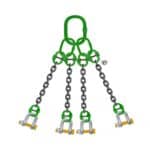
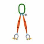
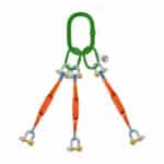
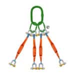
Handling Complex Sling Configurations
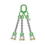
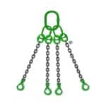
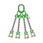
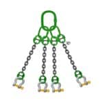
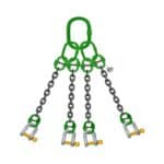
Complex sling configurations, such as multiple slings or bridle arrangements, can complicate the calculation of sling tensions and load distribution.
To handle complex sling configurations:
- Break Down into Simple Components: Break down the complex sling configuration into simpler components, such as individual slings or pairs of slings.
- Calculate Sling Tensions: Calculate the sling tensions for each component, taking into account the geometry of the sling arrangement. Use trigonometric functions or vector analysis to determine the sling tensions.
- Determine Load Distribution: Determine how the load is distributed among the various slings and calculate the load on each lifting point.
- Verify Capacity: Verify that the slings and the spreader beam have sufficient capacity to handle the calculated sling tensions and load distribution.
What To Do if Calculations Exceed Capacity
If your calculations indicate that the spreader beam’s capacity is insufficient for the intended load, take the following steps:
1. Re-evaluate Load: Re-evaluate the load to ensure that the weight and dimensions are accurate and that all load factors have been considered.
2. Reduce Load: If possible, reduce the load by removing unnecessary components or using lighter materials.
3. Increase Beam Capacity: Increase the beam’s capacity by using a larger beam with a higher section modulus or by reinforcing the existing beam.
4. Reduce Angle of Lift: Reduce the angle of lift to decrease the sling tensions and the bending moment on the beam.
5. Add Additional Lifting Points: Add additional lifting points to distribute the load more evenly and reduce the stress on each point.
6. Consult an Engineer: Consult a qualified engineer to review your calculations and recommend alternative solutions.
The Future of Spreader Beam Capacity Calculations
The field of spreader beam capacity calculations is on the cusp of significant advancements, driven by technological innovations and an increasing emphasis on safety and efficiency.
The Future of Spreader Beams
Emerging trends in spreader beam design and application include:
- Advanced Materials: Increased use of high-strength, lightweight materials such as carbon fiber composites and advanced alloys to enhance strength-to-weight ratios.
- Smart Beams: Integration of sensors and monitoring systems to provide real-time data on load, stress, and deflection, enabling proactive maintenance and preventing overloads.
- Modular Designs: Development of modular spreader beams that can be easily configured and adapted to different load sizes and lifting requirements.
- Automated Calculations: Use of sophisticated software and algorithms to automate the calculation of spreader beam capacity, reducing the risk of errors and improving efficiency.
The Benefits of AI
Artificial intelligence (AI) is poised to revolutionize spreader beam capacity calculations by providing more accurate, efficient, and reliable solutions. AI-powered tools can:
- Automate Calculations: Automate complex calculations, reducing the risk of human errors and saving time.
- Optimize Designs: Optimize spreader beam designs based on specific load requirements and material properties.
- Predict Failures: Predict potential failures based on real-time data from sensors and monitoring systems.
- Improve Safety: Improve safety by providing early warnings of potential overloads or structural issues.
“The integration of AI into lifting and rigging operations will transform the industry, enabling safer and more efficient lifting practices.” – John Smith, Lead Safety Inspector
Conclusion: Mastering Spreader Beam Capacity
You’ve successfully navigated the critical steps involved in determining spreader beam capacity, from understanding the fundamental principles to performing detailed calculations. By accurately determining the load weight, calculating the angle of lift, understanding bending and shear stress, and accounting for safety factors, you can ensure the safety and efficiency of your lifting operations. Remember that precise calculations, thorough documentation, and adherence to industry standards are essential for mitigating risks and preventing accidents. You now have the knowledge to confidently handle spreader beam capacity calculations in 2026. We’re here to help you with your lifting needs!
FAQ Section
Q: What is a spreader beam and why is it used?
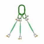
A: A spreader beam, also known as a lifting beam, is a piece of rigging equipment used to lift heavy or awkwardly shaped loads safely and efficiently. It distributes the load weight evenly, reducing stress on the lifting mechanism and preventing damage to the load.
Q: How do I determine the correct size of spreader beam for my lifting application?
A: To determine the correct size of spreader beam, you need to consider the load weight, dimensions, lifting points, angle of lift, and material properties. Perform detailed calculations to ensure that the beam has sufficient capacity to handle the applied load with an appropriate safety factor.
Q: What is WLL calculation?
A: WLL stands for Working Load Limit. WLL calculation is the process of determining the maximum load that a lifting device or piece of equipment can safely handle. It is a critical factor in ensuring safe lifting practices and preventing accidents.
Q: What are the key factors that affect lifting beam capacity?
A: The key factors that affect lifting beam capacity include: Load weight, Angle of lift, Material properties (yield strength, tensile strength), Section modulus, Bending moment, Shear stress,