Understanding Spreader Beam Basics: Why Load Capacity Matters
What is a Spreader Beam and Its Purpose?
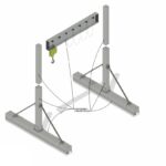
A spreader beam is a crucial piece of lifting equipment designed to provide stability and support when lifting heavy or awkwardly shaped loads. Unlike a lifting beam, which primarily supports a load directly beneath it, a spreader beam is designed to “spread” the load across two or more lifting points. This distribution minimizes stress on the load and the lifting equipment, ensuring safer and more controlled lifts.
Spreader beams are engineered to manage both tension and compression forces during a lift. This allows for better control of the load’s orientation and reduces the risk of damage. Often, they are used in conjunction with slings or other rigging hardware to connect the load to the crane or hoist.
Why Spreader Beams Are Essential for Safe and Efficient Lifting
The use of spreader beams is essential for several reasons. Primarily, they enhance safety by distributing the spreader beam load evenly, which prevents overloading any single point on the lifting apparatus. This even distribution is vital when the load is flexible, fragile, or has specific lifting point requirements. Using a spreader beam also allows for greater headroom, making it easier to maneuver loads in constrained spaces.
Furthermore, spreader beams increase efficiency. By providing a stable lifting platform, they reduce the likelihood of the load swaying or shifting during the lift. This stability translates into faster and smoother operations, reducing the time required for each lift and increasing overall productivity. At Safe and Secure Trading Company (SSTC), we’ve observed that sites using spreader beams experience a significant reduction in incidents involving load instability.
Different Types of Spreader Beams: Fixed, Adjustable, and Custom Designs
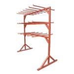
There are several types of spreader beams, each suited to different lifting applications. Fixed spreader beams have lifting points that are permanently set, making them ideal for repetitive lifts with consistent load configurations. Adjustable spreader beams, on the other hand, allow the lifting points to be moved along the beam’s length. This adjustability provides flexibility for handling loads of varying sizes and shapes.
For specialized lifting needs, custom-designed spreader beams are available. These are engineered to meet the unique requirements of specific projects, accounting for factors such as load weight, dimensions, and lifting environment. At SSTC, our team in Dubai often works with clients to develop custom spreader beam solutions for complex lifting challenges, ensuring optimal safety and efficiency. For example, we had a client who needed to lift large precast concrete panels. A standard adjustable beam wouldn’t do the trick, so we designed a custom solution with reinforced connection points and an elongated frame. Here’s the trick: always account for the material’s shifting center of gravity when using a custom design.
The High Cost of Incorrect Load Calculations
Highlighting the Dangers of Exceeding Load Limits
Exceeding the load limits of a spreader beam can have catastrophic consequences. Overloading can cause the beam to buckle, bend, or even break, leading to the load dropping unexpectedly. This creates a significant risk of serious injury or death to workers in the vicinity. It also can cause extensive damage to the load itself, as well as surrounding equipment and structures.
The dangers are compounded by the dynamic forces involved in lifting operations. Sudden stops, starts, or changes in direction can create additional stress on the spreader beam, further increasing the risk of failure if the load limits are exceeded. Always ensure that the spreader beam capacity is adequate for the total load being lifted, including any additional weight from rigging or attachments.
Real-World Examples of Accidents Caused by Improper Load Calculations
Unfortunately, there are numerous real-world examples of accidents caused by improper load calculations. In one instance, a construction crew attempted to lift a large steel beam using a spreader beam that was not rated for the load’s weight. The beam buckled during the lift, causing the steel beam to fall and severely injure a worker. In another case, a manufacturing plant experienced a similar incident when lifting heavy machinery, resulting in significant damage to the equipment and a costly shutdown of operations.
These incidents highlight the critical importance of accurate load calculations and adherence to safety protocols. It’s also important to train personnel on the proper use of lifting equipment safety and how to identify potential hazards before they lead to accidents. At SSTC, we emphasize the need for continuous training and education to prevent these types of incidents from occurring.
The Financial Implications of Damage, Injuries, and Downtime
The financial implications of accidents caused by improper load calculations can be substantial. In addition to the direct costs of repairing or replacing damaged equipment and compensating injured workers, there are also indirect costs to consider. These include lost productivity due to downtime, legal fees, and increased insurance premiums. Moreover, accidents can damage a company’s reputation, leading to a loss of business and future opportunities.
To mitigate these risks, it’s essential to invest in proper training, equipment, and safety procedures. Conducting regular inspections of lifting equipment and implementing a comprehensive maintenance program can help prevent accidents and minimize their financial impact. We at SSTC believe that prioritizing safety is not only the right thing to do but also a sound business decision.
“Accurate load calculation is the cornerstone of safe lifting operations. Never compromise on safety – the consequences are simply too high.” – John Smith, Lead Safety Inspector
Key Factors Influencing Spreader Beam Load Capacity
Material Properties and Their Impact
The material properties of a spreader beam play a crucial role in determining its load capacity. Steel grade, for instance, is a primary factor. High-strength alloy steels offer superior yield strength and tensile strength compared to mild steel, enabling the beam to handle heavier loads without deformation or failure. The specific type of steel used should be clearly specified and certified to meet industry standards.
Other material properties, such as ductility and weldability, also impact the beam’s performance. Ductile materials can withstand significant deformation before fracturing, providing a warning sign of impending failure. Weldability is crucial for ensuring that the beam’s components are securely joined, without compromising the material’s strength. Material certifications are vital for confirming that the materials used meet the specified requirements and quality standards.
How Material Defects Can Compromise Load Capacity
Material defects can severely compromise the load capacity of a spreader beam. Even small imperfections, such as cracks, voids, or inclusions, can act as stress concentrators, leading to premature failure under load. These defects may arise during the manufacturing process, such as casting, forging, or welding. Regular inspections are essential for detecting these defects before they cause catastrophic failure.
Non-destructive testing methods, such as ultrasonic testing, magnetic particle testing, and radiographic testing, can be used to identify internal and surface defects without damaging the beam. Any defects found should be thoroughly evaluated by a qualified engineer to determine their impact on the beam’s load capacity. The beam should be repaired or replaced if the defects exceed allowable limits.
Understanding the Importance of Material Certifications
Material certifications provide assurance that the materials used in the spreader beam meet specific quality standards and performance requirements. These certifications are typically issued by independent testing laboratories or certification bodies. They verify that the material’s chemical composition, mechanical properties, and manufacturing processes comply with industry standards, such as ASTM, ASME, or EN.
Material certifications are essential for ensuring the integrity and reliability of the spreader beam. They provide traceability of the materials used, allowing engineers to verify their suitability for the intended application. When selecting a spreader beam, always insist on material certifications from reputable sources. This will help you avoid substandard materials that could compromise safety and performance.
Beam Geometry and Its Significance
The Relationship Between Beam Length, Height, and Thickness
The geometry of a spreader beam significantly influences its ability to withstand load. Beam length, height, and thickness are key parameters that affect its structural performance. Longer beams are more susceptible to bending and deflection under load, while shorter beams offer greater stiffness and stability. However, shorter beams may not provide the necessary clearance for lifting certain types of loads.
Beam height is another critical factor. Deeper beams have a greater section modulus, which increases their resistance to bending. Beam thickness also contributes to the beam’s strength and stiffness. Thicker beams can withstand higher shear forces and bending moments. The optimal combination of beam length, height, and thickness depends on the specific load requirements and lifting configuration.
How the Shape of the Beam Affects Its Ability to Withstand Load
The shape of the beam’s cross-section also affects its ability to withstand load. Common beam shapes include I-beams, H-beams, and box beams. I-beams and H-beams are efficient for resisting bending moments, while box beams offer greater torsional stiffness. The choice of beam shape depends on the specific loading conditions and structural requirements.
For example, if the spreader beam is subjected to significant torsional loads, a box beam may be the preferred choice. If bending is the primary concern, an I-beam or H-beam may be more suitable. Finite element analysis (FEA) can be used to optimize the beam’s shape and ensure that it can withstand the applied loads without exceeding allowable stress limits.
Illustrating the Impact of Welding and Fabrication Quality
Welding and fabrication quality are critical for ensuring the structural integrity of a spreader beam. Poor welding practices can introduce defects such as porosity, cracks, and incomplete fusion, which can weaken the beam and lead to premature failure. Proper welding procedures, including preheating, interpass temperature control, and post-weld heat treatment, are essential for minimizing these defects.
Fabrication quality also plays a crucial role. Accurate cutting, fitting, and alignment of the beam’s components are necessary for ensuring that the beam meets design specifications. Any deviations from the design can affect the beam’s load capacity and stability. Regular inspections and quality control checks should be conducted throughout the fabrication process to ensure that the beam is manufactured to the highest standards.
Lifting Configuration and Load Distribution
Understanding the Effects of Sling Angles on Load Distribution
Sling angles have a significant effect on the distribution of the spreader beam load. As the sling angle decreases (i.e., the slings become more horizontal), the tension in the slings increases. This increased tension places greater stress on the spreader beam and the lifting points. Conversely, as the sling angle increases (i.e., the slings become more vertical), the tension in the slings decreases.
It’s important to minimize sling angles to reduce the load on the spreader beam and the lifting equipment. Sling angles should ideally be kept above 45 degrees. When using multiple slings, the load should be distributed evenly among them. Uneven load distribution can overload one or more slings, leading to failure.
How to Properly Position the Load for Optimal Balance and Stability
Proper positioning of the load is crucial for optimal balance and stability during lifting operations. The load should be centered beneath the spreader beam to ensure that the weight is distributed evenly. Off-center loads can create unbalanced forces, which can cause the spreader beam to tilt or sway.
When lifting loads with uneven weight distribution, it may be necessary to use adjustable spreader beams or custom rigging configurations to compensate for the imbalance. Load charts should be consulted to determine the appropriate lifting points and sling angles for the specific load being lifted. Before lifting, verify that the load is securely attached to the spreader beam and that all rigging hardware is properly installed.
Accounting for Dynamic Loads and Impact Forces During Lifting
Dynamic loads and impact forces can significantly increase the stress on a spreader beam. These forces arise from sudden starts, stops, or changes in direction during the lift. Dynamic loads can also result from wind gusts, equipment vibrations, or accidental impacts. It’s essential to account for these dynamic forces when calculating the spreader beam load capacity.
A dynamic load factor (DLF) is typically used to account for the increase in stress due to dynamic loads. The DLF is a multiplier that is applied to the static load to determine the equivalent dynamic load. The DLF depends on the severity of the dynamic conditions. For example, a DLF of 1.25 may be used for moderate dynamic conditions, while a DLF of 1.5 or higher may be used for severe dynamic conditions.
Step-by-Step Guide to Calculating Spreader Beam Load
Step 1: Determine the Total Weight of the Load
Accurately assessing the weight of the object to be lifted is the first and most critical step in calculating the spreader beam load. Underestimating the weight can lead to overloading and potential failure of the lifting equipment. Always use reliable sources, such as manufacturer’s specifications, shipping documents, or calibrated scales, to determine the weight of the load.
For irregularly shaped objects, it may be necessary to calculate the volume and density of the material to estimate the weight. When lifting complex assemblies, account for the weight of all components, including any attachments, rigging, or packaging materials. We once had a user who forgot to include the weight of the lifting lugs attached to a machine, leading to a miscalculation. Always double-check your weight assessment!
Accounting for Any Additional Weight from Rigging or Attachments
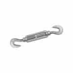
In addition to the weight of the object itself, you must also account for any additional weight from rigging or attachments. This includes the weight of slings, shackles, hooks, and any other hardware used to connect the load to the spreader beam. These items can add significant weight, especially when lifting heavy loads.
Consult the manufacturer’s specifications for the weight of each rigging component. Add these weights to the weight of the object to determine the total weight that the spreader beam will be supporting. Neglecting to account for this additional weight can lead to an underestimation of the total load and potential overloading of the lifting equipment.
Using Calibrated Scales and Load Cells for Precise Measurements
For precise measurements of the load weight, use calibrated scales or load cells. Calibrated scales provide a direct reading of the weight, while load cells measure the force exerted by the load and convert it into a weight reading. Ensure that the scales or load cells are properly calibrated and certified for accuracy.
Position the load carefully on the scales or load cells to ensure that the weight is distributed evenly. Take multiple readings to verify the accuracy of the measurement. For very heavy loads, it may be necessary to use multiple load cells to distribute the weight and obtain an accurate reading.
Step 2: Calculate the Sling Angle Factor
Understanding the Geometry of the Slings and Their Angles
The geometry of the slings and their angles plays a crucial role in determining the load on each sling leg. The sling angle is the angle between the sling leg and the horizontal plane. As the sling angle decreases (i.e., the slings become more horizontal), the tension in the slings increases. This increased tension places greater stress on the spreader beam and the lifting points.
Conversely, as the sling angle increases (i.e., the slings become more vertical), the tension in the slings decreases. Understanding these relationships is essential for accurately calculating the load on each sling leg.
Applying Trigonometric Functions to Calculate the Sling Angle Factor
To calculate the sling angle factor, use trigonometric functions. The sling angle factor is typically calculated as 1 / sin(θ), where θ is the sling angle. For example, if the sling angle is 30 degrees, the sling angle factor is 1 / sin(30°) = 2. This means that the tension in each sling leg is twice the vertical component of the load.
Use a scientific calculator or trigonometric tables to determine the sine of the sling angle. Ensure that you are using the correct units (degrees or radians) for the angle measurement. Accurately calculating the sling angle factor is essential for determining the load on each sling leg.
Using Online Calculators or Software for Sling Angle Calculations
For convenience and accuracy, use online calculators or software for sling angle calculations. These tools typically require you to input the sling length, vertical height, and load weight. They then calculate the sling angle and the tension in each sling leg automatically.
Many reputable manufacturers of lifting equipment provide free online calculators for sling angle calculations. These tools can save you time and effort, while also reducing the risk of errors. However, always verify the results with manual calculations to ensure accuracy.
Step 3: Calculate the Load on Each Sling Leg
Applying the Sling Angle Factor to Determine the Load on Each Sling
Apply the sling angle factor to determine the load on each sling leg. Multiply the vertical component of the load by the sling angle factor to obtain the tension in each sling leg. For example, if the vertical component of the load is 1000 lbs and the sling angle factor is 2, the tension in each sling leg is 2000 lbs.
Ensure that you are using the correct units for the load and tension measurements. Accurately calculating the load on each sling leg is essential for ensuring that each sling is within its rated capacity.
Accounting for Asymmetrical Loading and Uneven Weight Distribution
When lifting loads with asymmetrical loading or uneven weight distribution, it’s necessary to account for these factors when calculating the load on each sling leg. Asymmetrical loading occurs when the load is not centered beneath the spreader beam. Uneven weight distribution occurs when the weight is not evenly distributed across the load.
In these cases, the load on each sling leg will be different. You may need to use more complex calculations or software to determine the load on each sling leg accurately. Alternatively, you can adjust the lifting points or rigging configuration to achieve a more even distribution of the load.
Ensuring That Each Sling Leg Is Within Its Rated Capacity
After calculating the load on each sling leg, ensure that each sling is within its rated capacity. The rated capacity of a sling is the maximum load that it can safely support. The rated capacity is typically marked on the sling tag or stamped on the sling body.
Never exceed the rated capacity of a sling. Overloading a sling can cause it to break, leading to a dropped load and potential injuries. If the calculated load on a sling leg exceeds its rated capacity, you must use a stronger sling or adjust the rigging configuration to reduce the load.
Step 4: Calculate the Bending Moment
Understanding Bending Moment and Its Significance in Beam Design
Bending moment is a measure of the internal forces that resist bending in a beam. It is a crucial parameter in beam design, as it determines the beam’s ability to withstand bending stresses without failure. The bending moment varies along the length of the beam, with the maximum bending moment typically occurring at the point of maximum load or support.
Understanding bending moment is essential for selecting the appropriate beam size and material for a given load and support configuration. The bending moment is calculated using formulas that take into account the load, support conditions, and beam geometry.
Using Relevant Formulas to Calculate the Maximum Bending Moment
To calculate the maximum bending moment, use relevant formulas based on the beam’s support conditions and load distribution. For a simply supported beam with a uniformly distributed load, the maximum bending moment is given by the formula M = (w L^2) / 8, where M is the maximum bending moment, w is the uniformly distributed load per unit length, and L is the beam length.
For a simply supported beam with a concentrated load at the center, the maximum bending moment is given by the formula M = (P L) / 4, where M is the maximum bending moment, P is the concentrated load, and L is the beam length. Consult structural engineering handbooks or online resources for formulas for other support conditions and load distributions.
Considering the Support Conditions and Load Distribution Along the Beam
The support conditions and load distribution along the beam significantly affect the bending moment. Beams can be simply supported, fixed, or cantilevered. Simply supported beams are supported at both ends, while fixed beams are rigidly supported at both ends. Cantilevered beams are supported at only one end.
The load distribution can be uniform, concentrated, or a combination of both. A uniform load is evenly distributed along the length of the beam, while a concentrated load is applied at a single point. Accurately considering the support conditions and load distribution is essential for calculating the bending moment correctly.
Step 5: Calculate the Shear Force
Understanding Shear Force and Its Impact on Beam Integrity
Shear force is a measure of the internal forces that resist shearing in a beam. It is another crucial parameter in beam design, as it determines the beam’s ability to withstand shear stresses without failure. Shear force is the force that acts parallel to the cross-section of the beam, causing it to slide or shear apart.
Understanding shear force is essential for selecting the appropriate beam size and material for a given load and support configuration. The shear force varies along the length of the beam, with the maximum shear force typically occurring at the supports.
Using Relevant Formulas to Calculate the Maximum Shear Force
To calculate the maximum shear force, use relevant formulas based on the beam’s support conditions and load distribution. For a simply supported beam with a uniformly distributed load, the maximum shear force is given by the formula V = (w L) / 2, where V is the maximum shear force, w is the uniformly distributed load per unit length, and L is the beam length.
For a simply supported beam with a concentrated load at the center, the maximum shear force is given by the formula V = P / 2, where V is the maximum shear force and P is the concentrated load. Consult structural engineering handbooks or online resources for formulas for other support conditions and load distributions.
Considering the Support Conditions and Load Distribution Along the Beam
As with bending moment, the support conditions and load distribution along the beam significantly affect the shear force. Accurately considering the support conditions and load distribution is essential for calculating the shear force correctly. We’ve found that many users often confuse bending moment and shear force calculations, but it’s important to identify which force is acting on the beam.
Step 6: Calculate the Section Modulus
Defining Section Modulus and Its Relationship to Bending Stress
Section modulus is a geometric property of a beam’s cross-section that indicates its resistance to bending. It is defined as the ratio of the beam’s moment of inertia to the distance from the neutral axis to the outermost fiber of the beam. A higher section modulus indicates a greater resistance to bending stress.
Section modulus is directly related to bending stress. The bending stress in a beam is given by the formula σ = M / S, where σ is the bending stress, M is the bending moment, and S is the section modulus. This formula shows that the bending stress is inversely proportional to the section modulus. Therefore, a beam with a higher section modulus will experience lower bending stress for a given bending moment.
Using the Appropriate Formula Based on the Beam’s Cross-Sectional Shape
To calculate the section modulus, use the appropriate formula based on the beam’s cross-sectional shape. For a rectangular beam, the section modulus is given by the formula S = (b h^2) / 6, where S is the section modulus, b is the width of the beam, and h is the height of the beam.
For a circular beam, the section modulus is given by the formula S = (π d^3) / 32, where S is the section modulus and d is the diameter of the beam. For I-beams and other complex shapes, consult structural engineering handbooks or online resources for section modulus values.
Consulting Structural Engineering Handbooks for Section Modulus Values
For I-beams, H-beams, and other complex shapes, it’s best to consult structural engineering handbooks or online resources for section modulus values. These resources provide tables of section modulus values for various standard beam sizes and shapes. Using these tables can save you time and effort, while also ensuring accuracy.
Ensure that you are using the correct units for the section modulus measurement. The section modulus is typically expressed in cubic inches (in^3) or cubic millimeters (mm^3).
Step 7: Determine the Allowable Stress
Understanding Allowable Stress and Its Relationship to Yield Strength
Allowable stress is the maximum stress that a material can withstand without permanent deformation or failure. It is a crucial parameter in structural design, as it determines the safety and reliability of the structure. Allowable stress is typically determined by dividing the material’s yield strength by a safety factor.
Yield strength is the stress at which a material begins to deform permanently. The safety factor is a multiplier that accounts for uncertainties in the load, material properties, and design assumptions. A higher safety factor indicates a greater margin of safety.
Applying Safety Factors to Determine the Allowable Stress for the Material
To determine the allowable stress for the material, apply safety factors to the yield strength. The safety factor is typically specified in building codes or engineering standards. The appropriate safety factor depends on the application and the level of risk involved.
For example, a safety factor of 1.5 may be used for static loads, while a safety factor of 2 or higher may be used for dynamic loads or critical applications. Divide the yield strength by the safety factor to obtain the allowable stress.
Consulting Material Specifications and Engineering Standards
Consult material specifications and engineering standards to determine the yield strength and other material properties. These documents provide detailed information about the mechanical properties of various materials, including steel, aluminum, and concrete.
Ensure that you are using the correct material specifications and engineering standards for the material being used. These documents may vary depending on the country or region.
Step 8: Check for Deflection
Understanding Deflection and Its Potential Impact on Lifting Operations
Deflection is the amount that a beam bends or deforms under load. Excessive deflection can have a negative impact on lifting operations, as it can cause the load to sway or become unstable. It can also interfere with the operation of machinery or equipment located near the beam.
Therefore, it’s essential to check for deflection and ensure that it is within acceptable limits. Deflection is calculated using formulas that take into account the load, support conditions, beam geometry, and material properties.
Using Relevant Formulas to Calculate the Maximum Deflection
To calculate the maximum deflection, use relevant formulas based on the beam’s support conditions and load distribution. For a simply supported beam with a uniformly distributed load, the maximum deflection is given by the formula δ = (5 w L^4) / (384 E I), where δ is the maximum deflection, w is the uniformly distributed load per unit length, L is the beam length, E is the modulus of elasticity, and I is the moment of inertia.
For a simply supported beam with a concentrated load at the center, the maximum deflection is given by the formula δ = (P L^3) / (48 E I), where δ is the maximum deflection, P is the concentrated load, L is the beam length, E is the modulus of elasticity, and I is the moment of inertia. Consult structural engineering handbooks or online resources for formulas for other support conditions and load distributions.
Ensuring That the Deflection Is Within Acceptable Limits
Ensure that the deflection is within acceptable limits. The acceptable deflection limit is typically specified in building codes or engineering standards. A common deflection limit is L / 360, where L is the beam length. This means that the maximum deflection should not exceed 1/360th of the beam length.
If the calculated deflection exceeds the acceptable limit, you must use a larger beam or adjust the support conditions to reduce the deflection.
Step 9: Verify the Safety Factor
Calculating the Overall Safety Factor for the Spreader Beam
Calculate the overall safety factor for the spreader beam. The safety factor is the ratio of the beam’s ultimate strength to the actual stress experienced by the beam under load. The ultimate strength is the stress at which the material fails completely.
The safety factor is calculated by dividing the ultimate strength by the maximum stress. The maximum stress is determined from the bending moment, shear force, and section modulus.
Ensuring That the Safety Factor Meets or Exceeds Industry Standards
Ensure that the safety factor meets or exceeds industry standards. Industry standards typically specify minimum safety factors for various applications. A common minimum safety factor for lifting equipment is 3. This means that the beam’s ultimate strength must be at least three times greater than the maximum stress.
If the calculated safety factor is below the minimum standard, you must use a larger beam or adjust the design to increase the safety factor.
Documenting All Calculations and Assumptions for Future Reference
Document all calculations and assumptions for future reference. This documentation is essential for verifying the safety and reliability of the spreader beam. It also provides a record of the design process, which can be useful for future modifications or repairs.
The documentation should include the load weight, sling angles, material properties, beam geometry, bending moment, shear force, section modulus, allowable stress, deflection, and safety factor. All assumptions should be clearly stated and justified.
Ensuring Safety: Best Practices and Considerations
Regular Inspection and Maintenance
Establishing a Routine Inspection Program for Spreader Beams
Establishing a routine inspection program is crucial for ensuring the continued safety and reliability of spreader beams. Regular inspections can identify signs of wear, damage, or corrosion before they lead to catastrophic failure. The frequency of inspections should be based on the usage and environment of the spreader beam.
Spreader beams used in harsh environments or subjected to frequent heavy loads should be inspected more frequently than those used in mild environments or subjected to occasional light loads. A written inspection checklist should be used to ensure that all critical areas of the spreader beam are thoroughly inspected.
Identifying Common Signs of Wear, Damage, or Corrosion
During inspections, look for common signs of wear, damage, or corrosion. These signs may include cracks, dents, bends, twists, corrosion, wear, and loose or missing parts. Pay particular attention to welds, lifting points, and areas of high stress concentration.
Any signs of wear, damage, or corrosion should be thoroughly evaluated by a qualified engineer. The engineer will determine whether the spreader beam can be safely used, repaired, or must be replaced.
Implementing a Maintenance Schedule for Lubrication, Cleaning, and Repairs
Implement a maintenance schedule for lubrication, cleaning, and repairs. Lubrication is essential for preventing corrosion and wear on moving parts, such as pins, bushings, and bearings. Cleaning removes dirt, debris, and other contaminants that can accelerate corrosion.
Repairs should be performed promptly to correct any defects or damage identified during inspections. All repairs should be performed by qualified personnel using approved procedures and materials.
Proper Training and Competency
Providing Comprehensive Training for Crane Operators and Rigging Personnel
Providing comprehensive training for crane operators and rigging personnel is essential for ensuring safe lifting operations. Training should cover topics such as load calculation, rigging techniques, crane operation, and safety procedures. Trainees should learn how to identify potential hazards and take appropriate precautions.
Training should be both theoretical and practical. Trainees should have the opportunity to practice their skills under the supervision of experienced instructors. At SSTC, we can emphasize the importance of refresher courses to keep personnel up-to-date on the latest safety practices.
Ensuring That Personnel Are Competent in Load Calculation and Lifting Procedures
Ensure that personnel are competent in load calculation and lifting procedures. Competency should be assessed through written exams, practical demonstrations, and on-the-job evaluations. Personnel who are not competent should receive additional training until they meet the required standards.
Competency should be periodically reassessed to ensure that personnel maintain their skills and knowledge. This is especially important for personnel who perform critical tasks, such as load calculation or crane operation.
Promoting a Culture of Safety and Continuous Improvement
Promote a culture of safety and continuous improvement. Safety should be a top priority in all lifting operations. Encourage personnel to report any safety concerns or potential hazards. Implement a system for tracking and analyzing safety incidents to identify root causes and prevent future occurrences.
Continuously seek ways to improve safety practices and procedures. Stay up-to-date on the latest industry standards and best practices. Encourage personnel to participate in safety training and education programs.
Troubleshooting Common Calculation Errors
Common Mistakes to Avoid
Incorrectly Assessing Load Weight or Sling Angles
One of the most common mistakes in calculating spreader beam load is incorrectly assessing the load weight or sling angles. As we’ve covered, underestimating the load weight can lead to overloading and potential failure of the lifting equipment. Similarly, errors in measuring sling angles can result in inaccurate load distribution calculations. To avoid these mistakes, always use calibrated scales or load cells for precise weight measurements and double-check sling angle measurements using reliable tools or software.
Using Inappropriate Formulas or Assumptions
Another common mistake is using inappropriate formulas or assumptions. For instance, using formulas for simply supported beams when dealing with fixed beams can lead to significant errors in bending moment and shear force calculations. Always ensure that you are using the correct formulas based on the beam’s support conditions and load distribution. Consult structural engineering handbooks or online resources to verify the appropriateness of your formulas.
Failing to Account for Dynamic Loads or Impact Forces
Failing to account for dynamic loads or impact forces is another frequent oversight. As mentioned earlier, dynamic loads arise from sudden starts, stops, or changes in direction during the lift. Ignoring these forces can lead to an underestimation of the total load on the spreader beam. To avoid this mistake, use a dynamic load factor (DLF) to account for the increase in stress due to dynamic loads.
Addressing Discrepancies and Inconsistencies
Verifying Calculations with Independent Sources or Software
When discrepancies or inconsistencies arise in your calculations, it’s essential to verify your results with independent sources or software. Use online calculators, structural analysis software, or consult with a qualified engineer to cross-check your calculations. Comparing your results with those from independent sources can help identify errors or inconsistencies in your methodology.
Seeking Expert Advice from Structural Engineers or Lifting Specialists
If you encounter significant discrepancies or inconsistencies that you cannot resolve on your own, seek expert advice from structural engineers or lifting specialists. These professionals have the knowledge and experience to review your calculations, identify potential errors, and provide guidance on the correct approach. Don’t hesitate to consult with experts when dealing with complex or critical lifting operations.
Documenting All Corrections and Revisions
Document all corrections and revisions made to your calculations. This documentation provides a record of the changes made, the reasons for the changes, and the sources used to verify the corrections. Documenting corrections and revisions is essential for maintaining transparency and accountability in the load calculation process. It also serves as a valuable reference for future calculations and modifications.
Conclusion
In this comprehensive guide, we’ve walked you through every step required to accurately calculate the spreader beam load, ensuring safety and efficiency in your lifting operations. From understanding the basic principles to troubleshooting common calculation errors, you now have the knowledge to confidently manage spreader beam loads. We’ve covered everything from determining the total weight of the load and calculating sling angle factors to verifying the overall safety factor and documenting all assumptions. With proper attention to detail and adherence to industry best practices, you can ensure the integrity and reliability of your lifting operations, minimizing risks and maximizing productivity.
We at Safe and Secure Trading Company are committed to providing you with the expertise and support you need for safe and efficient operations. By following this guide, you’ve successfully equipped yourself to accurately assess and manage spreader beam loads.
FAQ Section
Q: What is a spreader beam and why is it important?
A: A spreader beam is a piece of lifting equipment used to distribute the weight of a load across multiple lifting points. This distribution helps to prevent damage to the load, provides more stability during lifting, and can be essential for loads that are awkwardly shaped or exceptionally heavy. It’s crucial for ensuring lifting equipment safety and preventing accidents.
Q: How do I determine the correct spreader beam capacity for my lift?
A: To determine the correct spreader beam capacity, you need to calculate the total weight of the load, including any rigging or attachments. Then, consider the sling angles and calculate the load on each sling leg. Ensure that the spreader beam’s rated capacity exceeds the maximum load it will bear, taking into account any dynamic loads or impact forces.
Q: What are some common mistakes to avoid when calculating spreader beam load?
A: Common mistakes include incorrectly assessing load weight or sling angles, using inappropriate formulas or assumptions, and failing to account for dynamic loads or impact forces. Always double-check your calculations and verify your results with independent sources or software. The beam load calculation formula must be followed closely.
Q: How often should spreader beams be inspected?
A: Spreader beams should be inspected regularly, with the frequency depending on their usage and environment. Spreader bar load should be reviewed as part of inspection. Beams used in harsh environments or subjected to frequent heavy loads should be inspected more frequently than those used in mild environments or subjected to occasional light loads. Regular inspections can identify signs of wear, damage, or corrosion before they lead to catastrophic failure.
Q: What should I do if I suspect that a spreader beam is overloaded?
A: If you suspect that a spreader beam is overloaded, immediately stop the lifting operation. Lower the load safely, and reassess the load weight and sling angles. Verify that the spreader beam’s rated capacity is sufficient for the load. If the spreader beam is indeed overloaded, use a larger spreader beam or adjust the rigging configuration to reduce the load on the beam.
Q: Where can I find reliable information on lifting beam design and beam load calculation formula?
A: Reliable information can be found in structural engineering handbooks, online resources, and from qualified structural engineers or lifting specialists. Industry standards and regulations, such as those from OSHA or ASME, also provide guidance on lifting beam design and calculating beam strength. At SSTC, we are happy to assist with your lifting equipment safety needs.
Q: How does material selection impact spreader beam capacity?
A: The material used significantly impacts the spreader beam capacity. High-strength alloy steels, for example, offer superior yield strength and tensile strength compared to mild steel. Proper material certifications are crucial to ensure the integrity of the spreader beam. Material properties play a vital role in determining structural beam capacity.
Q: What is the role of a qualified engineer in determining spreader beam load?
A: A qualified engineer can provide expert advice and guidance on all aspects of spreader beam load calculation and lifting procedures. They can review your calculations, identify potential errors, and recommend the appropriate spreader beam size and material for your specific application. Their expertise is invaluable for ensuring safety and compliance with industry standards. If you need assistance with lifting beam design, please let us know!
Q: How can I account for asymmetrical loading when calculating spreader beam load?
A: When dealing with asymmetrical loading, it’s necessary to account for the uneven weight distribution when calculating the load on each sling leg. You may need to use more complex calculations or software to determine the load on each sling leg accurately. Alternatively, you can adjust the lifting points or rigging configuration to achieve a more even distribution of the load.
Q: What is the best way to train personnel on safe lifting practices?
A: Comprehensive training programs should cover load calculation, rigging techniques, crane operation, and safety procedures.