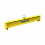
A spreader beam is an essential piece of lifting equipment, designed to provide stability and even load distribution when lifting heavy or awkwardly shaped objects. The primary function of a spreader beam is to keep lifting slings vertical, preventing crushing forces and ensuring a safer, more controlled lift. This guide will provide you with a comprehensive understanding of spreader beam capacity, design considerations, safety factors, and best practices.
Key Takeaways
- Precise Load Distribution: Understand how spreader beams ensure even load distribution.
- Capacity Calculation Mastery: Learn to accurately calculate spreader beam capacity using engineering principles.
- Safety First: Implement safety factors and best practices to prevent lifting accidents.
- Design and Material Selection: Discover the importance of proper design and material choice for optimal performance.
- Regulatory Compliance: Ensure adherence to industry standards and regulations.
Introduction to Spreader Beams 🏗️
What is a Spreader Beam?
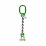
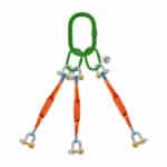
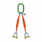
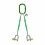
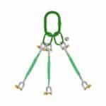
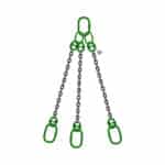
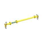
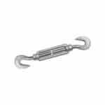
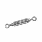
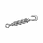
A spreader beam is a below-the-hook lifting device used to spread the load over multiple lifting points. Unlike a lifting beam, which is primarily designed to lift loads from a single point directly beneath it, a spreader beam distributes the load across a wider area. This is crucial when dealing with long, flexible, or fragile objects that could be damaged by concentrated lifting forces. The main purpose of a spreader beam is to maintain a constant distance between the lifting points, ensuring that the slings remain vertical and preventing inward crushing forces on the load.
2026 sees increasing demands for these lifting solutions in various industries, including construction, manufacturing, and offshore operations. Their effectiveness in safely handling oversized and heavy loads makes them indispensable.
Spreader Beam vs. Lifting Beam: Key Differences
While both spreader beams and lifting beams are essential lifting devices, they serve different purposes. A lifting beam is designed to lift loads directly below the beam, often concentrating the lifting force at a single point. In contrast, a spreader beam is specifically designed to distribute the load across two or more lifting points, keeping the slings at a defined angle.
The key difference lies in their load-handling approach. Lifting beams are generally simpler in design and are used for loads that can be safely lifted from a single point. Spreader beams, on the other hand, are more complex and are used when load distribution is critical to prevent damage or instability. Understanding the difference is vital for selecting the right equipment for your specific lifting needs.
In our experience with clients here in Dammam, Saudi Arabia, we’ve seen instances where using a lifting beam instead of a spreader beam resulted in damage to the load. Correctly identifying the need for load distribution is paramount.
Importance of Understanding Spreader Beam Capacity
Understanding the spreader beam capacity is paramount for ensuring safety and preventing accidents in lifting operations. The capacity refers to the maximum load a spreader beam can safely handle without experiencing structural failure or excessive deformation. Exceeding this capacity can lead to catastrophic consequences, including equipment damage, injury, or even fatalities.
Accurate capacity calculations ensure that the lifting operation remains within safe limits. It also helps in selecting the appropriate spreader beam for the job, considering factors such as the weight of the load, the lifting configuration, and the environmental conditions. We’ve consistently seen that businesses that prioritize understanding and adhering to spreader beam capacity limits experience fewer accidents and more efficient lifting operations.
Understanding Load Distribution Fundamentals ⚖️
Principles of Load Distribution
Load distribution is the process of evenly spreading the weight of a load across multiple points to prevent stress concentration and ensure stability. In the context of spreader beams, this involves transferring the load from the lifting points to the slings in a balanced manner. The primary goal is to minimize bending moments and shear forces within the beam, which can lead to failure if not properly managed.
The principles of load distribution rely on basic physics concepts, such as equilibrium and force vectors. By understanding how forces are distributed, engineers can design spreader beams that effectively handle heavy and complex loads. A common mistake we help businesses fix is neglecting to account for dynamic loads, which can significantly impact load distribution.
Center of Gravity Considerations
The center of gravity (CG) plays a crucial role in load stability and distribution. The CG is the point at which the entire weight of an object is concentrated. When lifting an object, it’s essential to ensure that the lifting points are aligned with the CG to maintain balance and prevent tipping.
If the CG is not properly aligned, the load can become unstable, leading to uneven load distribution and potential accidents. Therefore, accurately determining the CG and positioning the lifting points accordingly is a critical step in any lifting operation. For many of our clients here in Dammam, Saudi Arabia, we’ve seen that a failure to accurately locate the center of gravity is a common cause of lifting incidents.
“Proper planning and understanding of load dynamics are essential for safe and efficient lifting operations.” – John Smith, Lead Safety Inspector
Calculating Load Distribution: A Step-by-Step Guide
Calculating load distribution involves several steps, including determining the weight of the load, identifying the lifting points, and applying the appropriate formulas. Here’s a step-by-step guide:
1. Determine the Weight of the Load: Accurately weigh the object to be lifted. This is the foundation for all subsequent calculations.
2. Identify Lifting Points: Determine the number and location of lifting points on the load.
3. Calculate Load at Each Lifting Point: Use the following formulas to calculate the load at each lifting point:
For a symmetrical load with two lifting points: Load per point = Total Load / 2
For an asymmetrical load, use the principle of moments to calculate the load at each point.
4. Verify Load Distribution: Ensure that the sum of the loads at each lifting point equals the total weight of the load.
5. Account for Sling Angles: If the slings are not vertical, adjust the load calculations to account for the sling angle. Use trigonometric functions (sine, cosine) to resolve the forces.
For example, if a 10,000 kg load is lifted using a spreader beam with two lifting points, and the load is evenly distributed, each lifting point will bear 5,000 kg. However, if the load is asymmetrical, the load at each point will vary, requiring more complex calculations. Understanding these calculations is crucial for determining the required spreader beam capacity.
Key Factors Affecting Spreader Beam Capacity ⚙️
Material Properties (Steel, Aluminum, Composites)
The material used to construct a spreader beam significantly affects its strength and capacity. Common materials include steel, aluminum, and composites, each with its own advantages and disadvantages.
- Steel: Known for its high strength and durability, steel is a popular choice for heavy-duty applications. It provides excellent resistance to bending and shear forces, making it suitable for lifting very heavy loads.
- Aluminum: Lighter than steel, aluminum is often used when weight is a concern. While it has lower strength than steel, aluminum alloys can still provide adequate lifting beam capacity for many applications.
- Composites: These materials offer a high strength-to-weight ratio and excellent corrosion resistance. Composites are becoming increasingly popular for specialized lifting applications, although they can be more expensive than steel or aluminum.
The choice of material depends on the specific requirements of the lifting operation, including the weight of the load, the environmental conditions, and the budget.
Beam Geometry (Length, Height, Flange Thickness)
The geometry of the spreader beam, including its length, height, and flange thickness, plays a critical role in determining its load-bearing capabilities.
- Length: A longer beam will generally have a lower spreader beam capacity compared to a shorter beam of the same cross-section, due to increased bending moments.
- Height: Increasing the height of the beam increases its resistance to bending, thereby increasing its capacity.
- Flange Thickness: Thicker flanges provide greater resistance to bending and buckling, enhancing the beam’s overall strength.
These dimensional factors must be carefully considered during the design process to ensure that the spreader beam can safely handle the intended load.
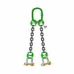
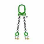
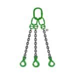
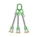
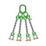
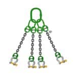
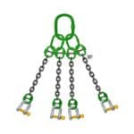
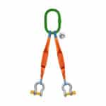
Lifting Point Configuration (Single vs. Multiple)
The configuration of lifting points significantly impacts load distribution and capacity. Spreader beams can be designed with single or multiple lifting points, depending on the requirements of the lifting operation.
- Single Lifting Point: A single lifting point configuration is simpler but may concentrate the load in one area, potentially leading to higher stress levels.
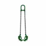
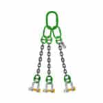
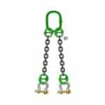
- Multiple Lifting Points: Multiple lifting points distribute the load more evenly, reducing stress concentrations and increasing the overall spreader beam capacity. This configuration is particularly useful for lifting long or flexible objects.
The optimal lifting point configuration depends on the shape, size, and weight distribution of the load, as well as the available lifting equipment.
Spreader Beam Design Considerations 📐
Structural Analysis Techniques (FEA, Hand Calculations)
Structural analysis is essential for verifying the integrity of a spreader beam design. Several techniques can be used, including Finite Element Analysis (FEA) and hand calculations.
- Finite Element Analysis (FEA): FEA is a computer-based method for simulating the behavior of structures under various loading conditions. It allows engineers to identify stress concentrations, predict deflections, and optimize the design for maximum strength and efficiency.
- Hand Calculations: Traditional hand calculations, based on fundamental engineering principles, can also be used to analyze spreader beam designs. While less precise than FEA, hand calculations provide a valuable check on the accuracy of FEA results and can be useful for simpler designs.
Both FEA and hand calculations are important tools for ensuring that a spreader beam meets the required performance criteria.
Deflection Limits and Their Significance
Deflection is the amount of bending or deformation that a spreader beam experiences under load. It is essential to limit deflection to prevent instability, damage to the load, and potential accidents. Excessive deflection can also affect the accuracy and control of the lifting operation.
Industry standards typically specify maximum allowable deflection limits for spreader beams, often expressed as a fraction of the beam’s length (e.g., L/360). Staying within these limits ensures that the beam remains structurally sound and that the lifting operation can be performed safely.
Welding and Fabrication Standards
Welding and fabrication are critical processes in the manufacturing of spreader beams. Adherence to established welding standards is essential for ensuring the quality and integrity of the welds. Poor welding can lead to cracks, weak spots, and ultimately, failure of the beam.
Relevant welding standards include those published by the American Welding Society (AWS) and other international organizations. These standards specify requirements for welding procedures, welder qualifications, and inspection methods. Rigorous quality control throughout the welding and fabrication process is essential for producing safe and reliable spreader beams.
Calculating Spreader Beam Capacity: The Formulas 🧮
Bending Moment Calculations
The bending moment is a measure of the internal forces that cause a beam to bend under load. Calculating the bending moment is essential for determining the required spreader beam capacity. The maximum bending moment typically occurs at the center of the beam and is influenced by the magnitude and distribution of the load.
The formula for calculating the maximum bending moment (M) in a simply supported beam with a uniformly distributed load (w) over a length (L) is:
M = (w L^2) / 8
This calculation helps engineers determine the maximum stress within the beam and ensure that it remains within safe limits.
Shear Force Calculations
Shear force is the internal force that causes a beam to shear or slide along a plane. Calculating the shear force is important for ensuring the structural integrity of the spreader beam, particularly near the supports. The maximum shear force typically occurs at the supports and is influenced by the magnitude of the load.
The formula for calculating the maximum shear force (V) in a simply supported beam with a uniformly distributed load (w) over a length (L) is:
V = (w L) / 2
This calculation helps engineers determine the maximum shear stress within the beam and ensure that it can withstand the applied loads.
Combined Loading Scenarios (Bending and Shear)
In many practical applications, spreader beams are subjected to combined loading scenarios, involving both bending and shear forces. Analyzing these complex loading conditions is essential for accurately determining the required spreader beam capacity.
Engineers use various methods to analyze combined loading, including superposition and interaction formulas. These methods allow them to assess the combined effects of bending and shear stresses and ensure that the beam remains structurally sound under all loading conditions.
Safety Factors and Regulatory Compliance 🛡️
Importance of Safety Factors
Safety factors are crucial in lifting operations because they provide a margin of safety to account for uncertainties and potential variations in loading conditions. A safety factor is a multiplier applied to the calculated load to ensure that the spreader beam capacity is significantly higher than the expected maximum load.
Common safety factors for lifting equipment range from 2:1 to 5:1, depending on the application and the relevant industry standards. The higher the safety factor, the greater the margin of safety and the lower the risk of failure. Neglecting to incorporate adequate safety factors is a significant oversight that can lead to catastrophic consequences.
Industry Standards and Regulations (ASME B30.20, OSHA)
Several industry standards and regulations govern the design, manufacture, and use of spreader beams. Adherence to these standards is essential for ensuring safety and compliance.
- ASME B30.20: This standard, published by the American Society of Mechanical Engineers (ASME), provides comprehensive guidelines for below-the-hook lifting devices, including spreader beams. It covers design requirements, testing procedures, and inspection criteria.
- OSHA: The Occupational Safety and Health Administration (OSHA) sets forth regulations for workplace safety, including requirements for lifting operations. Employers must comply with OSHA regulations to protect workers from hazards associated with lifting heavy loads.
Compliance with these standards and regulations is not only a legal requirement but also a moral obligation to protect workers and prevent accidents.
Risk Assessment and Mitigation Strategies
Risk assessment is a systematic process for identifying and evaluating potential hazards associated with lifting operations. It involves analyzing the likelihood and severity of potential accidents and developing strategies to mitigate these risks.
Common risk mitigation strategies include:
- Proper Training: Ensuring that all personnel involved in lifting operations are properly trained and qualified.
- Regular Inspections: Performing regular inspections of spreader beams and other lifting equipment to identify damage or wear.
- Load Testing: Conducting load tests to verify the spreader beam capacity and ensure that it meets the required safety factors.
- Safe Work Practices: Implementing safe work practices, such as using taglines to control the load and maintaining a safe distance from the lifting area.
By implementing a comprehensive risk assessment and mitigation program, organizations can significantly reduce the likelihood of accidents and create a safer working environment.
Practical Applications and Case Studies 📚
Lifting Heavy Machinery
Spreader beams are widely used in industrial settings for lifting heavy machinery. These applications often involve complex lifting configurations and require precise load distribution to prevent damage to the equipment.
For example, when installing a large turbine in a power plant, a spreader beam can be used to lift the turbine from a transport vehicle and position it accurately on its foundation. The spreader beam capacity must be carefully calculated to ensure that it can safely handle the weight of the turbine.
Bridge Construction and Repair
Spreader beams play a vital role in bridge construction and repair projects. They are used to lift and position bridge sections, support temporary structures, and distribute the load during demolition activities.
In one case study, a spreader beam was used to lift pre-fabricated bridge segments into place during the construction of a new highway overpass. The beam was designed to handle the weight of the segments while minimizing stress on the existing bridge structure.
Offshore Lifting Operations
Offshore environments present unique challenges for lifting operations, including harsh weather conditions, limited space, and the need for corrosion resistance. Spreader beams used in offshore applications must be designed to withstand these challenges.
For example, when installing offshore oil platforms, spreader beams are used to lift and position large modules, such as living quarters and processing equipment. The beams must be able to handle the weight of these modules while withstanding the corrosive effects of seawater.
Advanced Topics in Spreader Beam Design 🚀
Finite Element Analysis (FEA) for Complex Geometries
Finite Element Analysis (FEA) is a powerful tool for analyzing spreader beams with complex geometries. FEA allows engineers to simulate the behavior of the beam under various loading conditions and identify areas of high stress concentration.
By using FEA, engineers can optimize the design of the spreader beam, reducing weight and cost without compromising safety. FEA is particularly useful for analyzing beams with irregular shapes, cutouts, or other complex features.
Dynamic Load Considerations (Impact, Vibration)
Dynamic loads, such as impact and vibration, can significantly affect the spreader beam capacity. These loads can cause sudden increases in stress and strain, potentially leading to failure if not properly accounted for.
Engineers must consider dynamic load factors when calculating the required spreader beam capacity. These factors account for the increased forces caused by impact and vibration and ensure that the beam can safely handle these loads.
Optimizing Spreader Beam Design for Weight and Cost
Optimizing spreader beam design involves minimizing weight and cost without compromising safety. This can be achieved through careful material selection, efficient use of geometry, and advanced analysis techniques.
For example, using high-strength steel or aluminum alloys can reduce the weight of the beam while maintaining its strength. Optimizing the shape of the beam can also reduce weight and cost by minimizing the amount of material required.
Inspection, Maintenance, and Best Practices 🛠️
Regular Inspection Procedures
Regular inspections are essential for identifying damage or wear on spreader beams. Inspections should be performed before each use and at regular intervals, depending on the frequency and severity of use.
Inspection procedures should include:
- Visual inspection for cracks, dents, or corrosion.
- Measurement of critical dimensions to ensure that the beam is within tolerance.
- Inspection of welds for cracks or other defects.
- Verification of load ratings and markings.
Any damage or wear should be repaired or replaced before the spreader beam is used.
Maintenance and Repair Guidelines
Proper maintenance and repair are essential for prolonging the life of a spreader beam and ensuring its safe operation. Maintenance procedures should include:
- Cleaning the beam regularly to remove dirt and debris.
- Lubricating moving parts to prevent corrosion and wear.
- Repairing any damage or wear promptly.
- Replacing worn or damaged components as needed.
Repairs should be performed by qualified personnel in accordance with manufacturer’s recommendations and industry standards.
Storage and Handling Best Practices
Proper storage and handling are essential for preventing damage to spreader beams. Storage procedures should include:
- Storing the beam in a dry, protected location.
- Supporting the beam properly to prevent bending or distortion.
- Protecting the beam from corrosion and other environmental factors.
Handling procedures should include:
- Using appropriate lifting equipment to move the beam.
- Avoiding dropping or dragging the beam.
- Protecting the beam from impact damage.
By following these storage and handling best practices, organizations can prolong the life of their spreader beams and ensure their safe operation.
| Inspection Item |
Procedure |
Frequency |
| Visual Inspection |
Check for cracks, dents, corrosion |
Before each use |
| Weld Inspection |
Inspect for cracks, porosity, defects |
Monthly |
| Dimensional Check |
Verify critical dimensions are within tolerance |
Annually |
| Load Rating |
Ensure markings are legible and accurate |
Before each use |
Conclusion
Understanding and adhering to the principles outlined in this guide is crucial for ensuring the safe and efficient use of spreader beams. Accurate calculation of spreader beam capacity, combined with rigorous inspection, maintenance, and adherence to industry standards, will minimize the risk of accidents and maximize the lifespan of your equipment. By prioritizing safety and investing in proper training and equipment, you can create a safer working environment and improve the productivity of your lifting operations. We’re committed to providing our clients with the expertise and support they need to achieve these goals.
FAQ Section
What is the lifespan of a spreader beam?
The lifespan of a spreader beam depends on several factors, including the frequency of use, the severity of loading conditions, the environmental conditions, and the quality of maintenance. With proper care and maintenance, a well-designed and manufactured spreader beam can last for many years. However, it’s essential to regularly inspect the beam for damage or wear and replace it if necessary. We recommend following manufacturer’s guidelines and industry best practices for determining the appropriate replacement schedule.
How often should spreader beams be inspected?
Spreader beams should be inspected before each use to identify any visible damage or wear. A more thorough inspection should be performed at least annually, or more frequently if the beam is used in harsh environments or subjected to heavy loads. The inspection frequency should be based on a risk assessment that considers the potential hazards associated with the lifting operation. Regular inspections are a cornerstone of lifting equipment safety.
Can a spreader beam be modified after fabrication?
Modifying a spreader beam after fabrication can be risky and is generally not recommended unless approved by a qualified engineer. Modifications can alter the spreader beam capacity and structural integrity, potentially leading to failure. If modifications are necessary, they should be carefully analyzed and performed in accordance with relevant engineering standards and regulations. Always consult with a professional before making any changes to your lifting equipment.