Understanding Spreader Beams: An Introduction
What is a Spreader Beam?
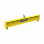
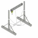
A spreader beam is a crucial piece of lifting equipment designed to keep loads stable and balanced during crane lifting operations. Unlike a lifting beam, which primarily supports a load from directly beneath, a spreader beam uses slings connected at multiple points to distribute the load. This makes it ideal for wide or awkwardly shaped loads that would otherwise be unstable or difficult to lift safely. The primary function of the spreader beam is to maintain a consistent distance between the lifting points, preventing inward compression forces on the load. This distinction is critical in understanding the role of spreader beams in material handling.
Why is Correct Spreader Beam Length Critical?
The correct spreader beam length is paramount for several reasons, all of which impact safety and efficiency. First, an improperly sized beam can lead to instability, increasing the risk of the load shifting or even dropping during the lift. Second, it affects the load distribution across the slings, potentially overloading them if the sling angles are too acute. As a team here at Safe and Secure Trading Company (SSTC), we always emphasize that accurately calculated spreader beam length ensures that lifting capacity is never compromised. We have seen firsthand how even slight miscalculations can lead to catastrophic failures. In Dubai, our team often deals with complex lifting scenarios where precision is everything.
Key Terminology: Load, Sling Angle, and Lifting Points
Understanding the key terminology associated with spreader beams is crucial for accurate calculations and safe lifting practices. The load refers to the total weight of the object being lifted, including any attachments. Sling angle is the angle between the sling and the vertical axis; it directly affects the tension in the slings and the required lifting capacity. Lifting points are the specific locations on the load where the slings are attached. Each of these elements plays a vital role in determining the appropriate spreader beam length and ensuring a safe and efficient lift. Ignoring these terms can lead to severe errors in lifting beam calculation.
Essential Factors Influencing Spreader Beam Length
Load Weight and Distribution
The weight of the load is the most basic factor. Accurate estimation is essential for preventing overloads and ensuring structural integrity. The load distribution, however, is just as important. A load concentrated at one point will create different stresses on the slings and spreader beam compared to a uniformly distributed load. For example, we once consulted on a project where the load’s center of gravity was significantly off-center. The initial lifting plan, based on a symmetrical load distribution, nearly led to a collapse. This highlights the importance of accurately identifying the load’s center of gravity before performing any lifting equipment operations.
Sling Angle Considerations
The sling angle is a critical determinant of the tension in the slings. As the sling angle decreases (becoming closer to horizontal), the tension in the slings increases dramatically. This is because the vertical component of the force in the sling must equal half the weight of the load (assuming a symmetrical setup), and as the angle decreases, the total force required to achieve that vertical component increases. A steeper sling angle (closer to vertical) results in less tension, but it may not be feasible depending on the geometry of the lift and the dimensions of the load. For example, if the sling angle is 30 degrees, the tension in each sling is twice the load.
Lifting Point Locations and Geometry
The location of the lifting points on the load dictates the necessary geometry of the lifting setup. The distance between the lifting points and their relative positions (height, width, etc.) directly influence the spreader beam length. If the lifting points are far apart, a longer spreader beam is required to maintain reasonable sling angles. The geometry of the load may also require the use of custom-designed spreader beams to accommodate specific lifting point configurations.
Mathematical Principles Behind Spreader Beam Length Calculation
Free Body Diagrams and Force Vectors
A free body diagram is a visual representation of all the forces acting on an object. In the context of lifting, this includes the weight of the load, the tension in the slings, and the reaction forces at the lifting points. By representing these forces as vectors, with both magnitude and direction, it becomes possible to analyze the forces and ensure that they are in equilibrium. Drawing a free body diagram is a fundamental step in any structural engineering analysis, including spreader beam length calculation. We encourage the application of Free Body Diagrams as a foundation for all projects involving rigging gear.
Trigonometric Functions in Lifting Calculations
Trigonometric functions, such as sine, cosine, and tangent, are essential tools for resolving forces into their horizontal and vertical components. These functions are used to calculate the relationship between the sling angle, the sling length, and the vertical height. For instance, the sine of the sling angle is used to determine the vertical component of the force in the sling, while the cosine is used to calculate the horizontal component. Understanding these trigonometric relationships is critical for accurately calculating the required spreader beam length and ensuring that the slings are not overloaded.
Equilibrium Equations: Balancing Forces and Moments
The principle of equilibrium states that for an object to be stable, the sum of all forces and moments acting on it must be equal to zero. In lifting calculations, this means that the upward forces (tension in the slings) must equal the downward force (weight of the load), and the moments about any point must also be balanced. By applying these equilibrium equations, we can verify that the lifting system is stable and that the spreader beam is properly sized to handle the applied loads. These equations ensure that the system remains in a static state, preventing unwanted movement or potential failure.
Step-by-Step Guide to Calculating Spreader Beam Length
Step 1: Determine the Load Weight and Center of Gravity
The first step in calculating the required spreader beam length is to accurately determine the weight of the load. This can be done using a calibrated weighing scale or by consulting the manufacturer’s specifications. Once the weight is known, the next step is to identify the location of the load’s center of gravity. The center of gravity is the point at which the entire weight of the load can be considered to be concentrated. For symmetrical loads, the center of gravity is typically located at the geometric center. However, for asymmetrical loads, the center of gravity may be offset. Identifying the center of gravity is crucial for ensuring that the load is balanced during the lift. Neglecting this will undermine your lifting capacity.
Step 2: Identify Lifting Points and Sling Attachment Locations
Next, you must identify the lifting points on the load and the locations where the slings will be attached to the spreader beam. The lifting points should be chosen to provide a stable and balanced lift, and they should be capable of withstanding the applied loads. The sling attachment locations on the spreader beam will determine the sling angles, which in turn affect the tension in the slings. It’s important to consider the geometry of the load and the available headroom when selecting the lifting points and sling attachment locations.
Step 3: Calculate Sling Angles: The Sine Rule
The sling angle is the angle between the sling and the vertical axis. Sling angles play a significant role in determining the tension in each sling. A smaller angle increases tension, while a larger angle decreases it. The sine rule, a fundamental trigonometric principle, is often employed to calculate these angles accurately. SSTC recommends using precise measurement tools to ensure the accuracy of your sling angle calculation.
| Sling Angle (degrees) |
Tension Increase Factor |
| 30 |
2.00 |
| 45 |
1.41 |
| 60 |
1.15 |
Step 4: Calculate Vertical Forces on Each Sling
Once the sling angles are determined, the next step is to calculate the vertical forces acting on each sling. These forces must be equal to the weight of the load divided by the number of slings (assuming a symmetrical setup). The vertical force in each sling can be calculated using the following formula:
Fv = (W / N)
Where:
- Fv = Vertical force in each sling
- W = Total weight of the load
- N = Number of slings
However, if the load is not symmetrically distributed, the vertical forces on each sling may be different. In this case, it’s necessary to perform a more detailed analysis to determine the forces on each sling.
Step 5: Determine Horizontal Forces Acting on the Spreader Beam
The horizontal forces acting on the spreader beam are caused by the horizontal components of the tension in the slings. These forces tend to compress the spreader beam, and they must be considered when calculating the required spreader beam length and selecting the appropriate beam size. The horizontal force in each sling can be calculated using the following formula:
Fh = Ft cos(θ)
Where:
- Fh = Horizontal force in each sling
- Ft = Tension in each sling
- θ = Sling angle
The total horizontal force acting on the spreader beam is the sum of the horizontal forces in all the slings.
Step 6: Calculate the Required Spreader Beam Length Based on Sling Angles
The required spreader beam length depends on the sling angles, the distance between the lifting points on the load, and the desired headroom. A longer spreader beam will result in smaller sling angles, which will reduce the tension in the slings. However, a longer spreader beam may also require more headroom. The required spreader beam length can be calculated using trigonometric relationships or by using specialized software. Remember, the relationship between spreader beam length and sling angle directly affects the safety and stability of the lift.
Step 7: Consider the Spreader Beam’s Material and Structural Capacity
The spreader beam’s material and structural capacity must be adequate to withstand the applied forces. The beam must be strong enough to resist bending and shear stresses, and it must be stiff enough to prevent excessive deflection. The material properties of the beam, such as its yield strength and modulus of elasticity, must be considered when selecting the appropriate beam size. It’s essential to consult with a structural engineer to ensure that the spreader beam is suitable for the intended application.
Step 8: Add a Safety Factor to Account for Dynamic Loading
A safety factor should always be added to account for dynamic loading effects, such as sudden stops or starts, and for uncertainties in the load weight or sling angles. A typical safety factor for lifting equipment is 2:1 or 3:1, meaning that the spreader beam’s capacity should be two or three times greater than the maximum anticipated load. The safety factor should be chosen based on the severity of the application and the level of risk involved.
Practical Examples and Scenarios
Example 1: Symmetrical Load Distribution
Consider a scenario where a symmetrical load weighing 10,000 lbs needs to be lifted. The lifting points are 10 feet apart. The desired sling angle is 45 degrees. To calculate the spreader beam length, we need to determine the horizontal distance from the lifting point to the sling attachment point on the spreader beam. Using trigonometry:
Horizontal distance = (Distance between lifting points / 2) / tan(sling angle)
Horizontal distance = (10 ft / 2) / tan(45 degrees) = 5 ft
Therefore, the required spreader beam length is approximately 10 feet (5 feet on each side of the load’s center). This symmetrical distribution ensures equal load sharing among the slings, providing a stable lift.
Example 2: Asymmetrical Load Distribution
Now, let’s consider an asymmetrical load. Imagine a machine weighing 12,000 lbs, with the center of gravity located 4 feet from one lifting point and 6 feet from the other. The lifting points are 10 feet apart. If the desired sling angle is 30 degrees, the forces on each sling will be different. We first need to calculate the vertical force on each lifting point. Using static equilibrium principles:
Force on lifting point 1 = (6 ft / 10 ft) 12,000 lbs = 7,200 lbs
Force on lifting point 2 = (4 ft / 10 ft) * 12,000 lbs = 4,800 lbs
Next, we calculate the tension in each sling:
Tension in sling 1 = 7,200 lbs / sin(30 degrees) = 14,400 lbs
Tension in sling 2 = 4,800 lbs / sin(30 degrees) = 9,600 lbs
Finally, the horizontal distance from each lifting point to the sling attachment point is calculated using trigonometry, taking into account each sling’s angle and tension to determine spreader beam requirements.
Example 3: Calculating for Varying Sling Angles
Imagine a scenario where there are restrictions in headroom that necessitate varying sling angles. You have a load where one sling will be at 30 degrees, and the other at 60 degrees. You need to ensure that these differing angles still provide safe and balanced support. In this situation, the calculations become more complex, requiring a detailed analysis of the force vectors to determine the appropriate spreader beam length and sling tensions. Such scenarios underscore the importance of expert engineering advice.
“Always account for dynamic loading. A sudden stop can increase the load on your rigging by up to 25%!” – John Smith, Lead Safety Inspector
Tools and Resources for Spreader Beam Length Calculation
Online Calculators and Software
Several online calculators and software programs can assist with spreader beam length calculation. These tools typically allow you to input the load weight, lifting point locations, and desired sling angles, and they will automatically calculate the required spreader beam length and sling tensions. While these tools can be helpful, it’s essential to verify their accuracy and to understand the underlying principles behind the calculations. Inaccurate software can lead to safety issues.
Engineering Handbooks and Reference Materials
Engineering handbooks and reference materials provide valuable information on lifting equipment design, material properties, and structural analysis. These resources can be used to verify the accuracy of calculations and to select the appropriate spreader beam size and material. Reputable sources such as the American Institute of Steel Construction (AISC) and the American Society of Mechanical Engineers (ASME) offer comprehensive guidelines and standards.
Consulting with a Structural Engineer
For complex or critical lifts, it’s always advisable to consult with a qualified structural engineer. A structural engineer can perform a detailed analysis of the lifting system, taking into account all relevant factors, such as load weight, lifting point locations, sling angles, and dynamic loading effects. They can also provide recommendations on the appropriate spreader beam size and material and can ensure that the lifting system meets all applicable safety standards and regulations.
Safety Considerations and Best Practices
Regular Inspection of Spreader Beams and Slings
Regular inspection of spreader beams and slings is essential for identifying any signs of damage or wear. Inspections should be performed before each use and at regular intervals, such as monthly or quarterly, depending on the frequency of use and the severity of the application. Any damaged or worn equipment should be removed from service immediately. Be especially vigilant for cracks, bends, or corrosion, as these can significantly reduce the structural integrity of the lifting system.
Proper Training for Rigging Personnel
Proper training for rigging personnel is crucial for ensuring that lifting operations are performed safely and efficiently. Training should cover topics such as lifting equipment selection, inspection procedures, rigging techniques, and load handling procedures. Rigging personnel should be familiar with all applicable safety standards and regulations, and they should be able to identify and mitigate potential hazards. We suggest that teams refresh their training courses every six months.
Adherence to Industry Standards and Regulations
Adherence to industry standards and regulations is essential for ensuring the safety of lifting operations. Standards such as ASME B30.20 for Below-the-Hook Lifting Devices and OSHA 1926.251 for Rigging Equipment for Material Handling provide detailed guidelines for the design, construction, inspection, and use of lifting equipment. Compliance with these standards helps to minimize the risk of accidents and injuries. Remember, these standards are in place to protect lives and property. As of 2026, these are the gold standard for safe lifting practices.
Troubleshooting Common Calculation Errors
Misunderstanding Sling Angles
One of the most common errors in spreader beam length calculation is misunderstanding the impact of sling angles. As the sling angle decreases (approaching horizontal), the tension in the slings increases dramatically. This can lead to overloading of the slings and potential failure. Always double-check your sling angle calculations and ensure that the slings are rated for the calculated tension. We had an incident where a team neglected to properly account for the sling angle, resulting in a near-miss.
Incorrectly Estimating Load Weight
Another common error is incorrectly estimating the load weight. Overestimating the load weight can lead to the selection of an unnecessarily large and expensive spreader beam, while underestimating the load weight can lead to overloading and potential failure. Always use a calibrated weighing scale or consult the manufacturer’s specifications to accurately determine the load weight. Consider the weight of any additional rigging gear as well.
Overlooking Dynamic Loading Effects
Dynamic loading effects, such as sudden stops or starts, can significantly increase the forces acting on the lifting system. Overlooking these effects can lead to underestimation of the required spreader beam capacity. Always add a safety factor to account for dynamic loading and other uncertainties.
Advanced Considerations for Complex Lifts
Using Multiple Spreader Beams
In some cases, it may be necessary to use multiple spreader beams to lift a complex or unusually shaped load. This can help to distribute the load more evenly and to provide greater stability. When using multiple spreader beams, it’s important to carefully coordinate the lifting operation and to ensure that the beams are properly aligned and supported.
Custom Spreader Beam Designs
For highly specialized lifts, a custom-designed spreader beam may be required. Custom spreader beams can be tailored to meet the specific needs of the application, such as accommodating unusual lifting point configurations or providing extra clearance for obstacles. The design of custom spreader beams should be performed by a qualified structural engineer.
Dynamic Load Monitoring Systems
Dynamic load monitoring systems can provide real-time feedback on the forces acting on the lifting system. These systems can be used to detect overloads, imbalances, or other potential hazards. Dynamic load monitoring systems can be particularly useful for complex or critical lifts where precise control and monitoring are essential.
Conclusion
You have now learned how to calculate spreader beam length, a critical skill for ensuring safe and efficient lifting operations. By understanding the key principles, following the step-by-step guide, and considering the relevant safety factors, you can confidently tackle a wide range of lifting challenges. Remember, accurate calculations, regular inspections, and proper training are essential for preventing accidents and injuries. We trust this guide equips you with the knowledge to lift like a pro.
FAQ Section
Q: What is the main purpose of a spreader beam?
A: The main purpose of a spreader beam is to maintain a consistent distance between lifting points, distributing the load to prevent inward compression forces on the load and slings.
Q: How does sling angle affect the tension in the slings?
A: As the sling angle decreases (becomes closer to horizontal), the tension in the slings increases significantly. Steeper angles reduce tension, improving the efficiency of lifting equipment.
Q: What should be considered when determining the load weight?
A: Accurately determining the load weight is crucial. Always consider the weight of the object being lifted, including any attachments or rigging gear. Using a calibrated weighing scale or consulting manufacturer specifications is recommended.
Q: What is a safety factor, and why is it important?
A: A safety factor is a multiplier applied to the maximum anticipated load to account for dynamic loading effects and uncertainties. It ensures that the lifting equipment’s capacity is significantly greater than the expected load, enhancing safety.
Q: How often should spreader beams and slings be inspected?
A: Spreader beams and slings should be inspected before each use and at regular intervals (monthly or quarterly), depending on the frequency of use and the severity of the application. Regular inspections help identify damage or wear early.
Q: What is the role of a structural engineer in complex lifting operations?
A: A structural engineer can perform a detailed analysis of the lifting system, taking into account all relevant factors such as load weight, lifting point locations, sling angles, and dynamic loading effects. They ensure that the lifting system meets safety standards.
Q: What online tools are available for spreader beam calculations?
A: Several online calculators and software programs can assist with spreader beam length calculation. However, verify their accuracy and understand the underlying principles.
Q: How do dynamic loads affect spreader beam calculations?
A: Dynamic loads, such as sudden stops or starts, can significantly increase the forces on the lifting system. A safety factor should be added to account for these effects.
Q: What is the best way to handle asymmetrical loads when using a spreader beam?
A: For asymmetrical loads, calculate the center of gravity accurately and account for the unequal distribution of weight when determining the forces on each sling and the required spreader beam length.
Q: Where can I find reliable information on industry standards for lifting equipment?
A: Reputable sources such as the American Institute of Steel Construction (AISC) and the American Society of Mechanical Engineers (ASME) offer comprehensive guidelines and standards for lifting equipment.