Choosing the right rigging screw for specific load angles can be tricky. Learn to avoid critical errors and ensure safety with our expert guide on rigging screw load considerations.
Rigging screws are essential components in various lifting and tensioning applications, but understanding rigging screw load, particularly the impact of load angle, is crucial for safety and efficiency. The rigging screw load is not always straightforward, especially when the lifting or tensioning force is applied at an angle. In this comprehensive guide, brought to you by the experts at Safe and Secure Trading Company (SSTC), we’ll delve into the common mistakes made when dealing with rigging screw load and provide detailed instructions on how to avoid them. Proper calculation and consideration of the load angle are paramount to prevent equipment failure, injuries, and costly downtime.
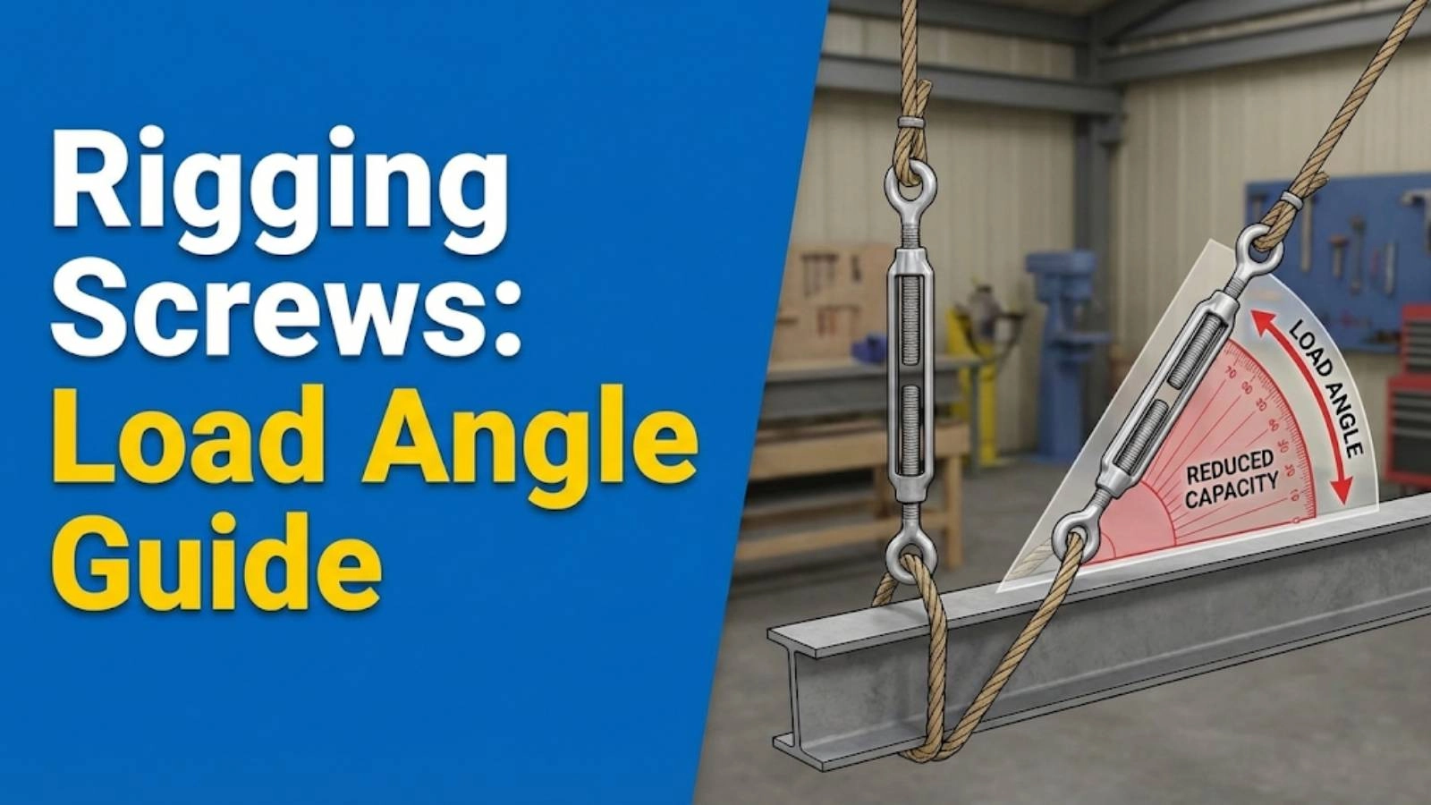
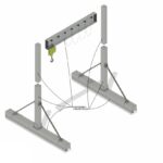
The load angle plays a pivotal role in determining the actual stress experienced by a rigging screw. When a load is applied vertically, the rigging screw bears the full weight directly. However, when the load is applied at an angle, the force is distributed differently, increasing the stress on the screw and other rigging components. The load angle affects the magnitude of the forces acting along different axes, requiring a more complex analysis to ensure safety. Neglecting to account for the load angle can lead to underestimating the actual force on the rigging screw, potentially causing it to fail under load. We at SSTC have seen instances where simple oversights in load angle calculation have led to significant accidents, underscoring the need for meticulous attention to detail.
The consequences of neglecting load angle calculations can be severe. Overloading a rigging screw, even by a small margin, can lead to deformation or outright failure. This not only jeopardizes the load being lifted or tensioned but also poses a significant risk to personnel and equipment in the vicinity. Moreover, equipment failure can result in costly repairs, project delays, and legal liabilities. Accurate measurements and thorough documentation are vital to ensuring the safety and integrity of rigging operations. Inaccurate measurements or assumptions can lead to flawed calculations, resulting in hazardous conditions. Therefore, riggers must be trained to use precise measuring tools and to meticulously record all relevant data.
The importance of accurate measurements and documentation cannot be overstated. Precise measurements form the foundation of accurate load calculations, ensuring that the rigging screws are appropriately sized and configured for the task at hand. Documentation provides a record of the calculations and decisions made, enabling verification and future reference. At our Dubai facility, we emphasize the use of calibrated instruments and standardized documentation procedures to minimize errors and ensure compliance with industry best practices. Remember, safety starts with precision.
[IMAGE: A diagram illustrating the effect of different load angles on the force experienced by a rigging screw]
Mistake #1: Ignoring the Vertical Load Component
One of the most common errors in rigging screw load calculation is ignoring the vertical load component (Wv). The vertical load component represents the portion of the total load that acts directly downwards. When a load is applied at an angle, only a fraction of the total force contributes to the vertical load, while the remainder contributes to the horizontal load. Failing to account for the vertical load component can lead to an underestimation of the actual stress on the rigging screw, potentially resulting in failure.
To calculate the vertical load component in angled lifts, you’ll typically use trigonometric functions. The vertical load component (Wv) can be calculated using the formula:
Wv = W cos(θ)
Where:
W is the total weight of the load
θ is the angle between the rigging screw and the vertical axis
For example, if a 1000 kg load is suspended at an angle of 30 degrees, the vertical load component would be:
Wv = 1000 kg cos(30°) ≈ 866 kg
Ignoring this calculation and assuming the vertical load is 1000 kg can lead to selecting an undersized rigging screw. SSTC recommends using online calculators or software tools to assist with these calculations and reduce the risk of error.
Several tools and resources are available to help with accurate vertical load calculation. Online calculators, such as those provided by engineering websites and rigging equipment manufacturers, can quickly compute the vertical load component given the total load and angle. Software tools, such as CAD programs and specialized rigging calculation software, offer more advanced capabilities for simulating and analyzing complex rigging scenarios. Additionally, reference tables and charts, commonly found in rigging handbooks and training materials, provide pre-calculated values for common load angles.
We once encountered a project where a team consistently overlooked the vertical load component, leading to several near-misses. After implementing a standardized calculation procedure and providing additional training, the team significantly reduced the risk of overloading rigging screws. This highlights the importance of integrating proper calculations into standard operating procedures.
Mistake #2: Overlooking the Horizontal Load Component
Just as important as the vertical load component is the horizontal load component (Wh). The horizontal load component is the portion of the total load that acts horizontally, perpendicular to the vertical axis. This component can create additional stress on the rigging system, particularly on anchor points and supporting structures. Ignoring the horizontal load component can lead to instability and potential failure, especially when dealing with angled lifts or tensioning applications.
To calculate the horizontal load component in angled lifts, you can use the following formula:
Wh = W sin(θ)
Where:
W is the total weight of the load
θ is the angle between the rigging screw and the vertical axis
Using the same example as before, with a 1000 kg load suspended at a 30-degree angle, the horizontal load component would be:
Wh = 1000 kg sin(30°) = 500 kg
This horizontal force must be considered when selecting anchor points and ensuring the stability of the rigging system. Failing to do so can cause the anchor points to fail or the entire system to become unstable.
Ignoring horizontal forces can have serious consequences. Horizontal forces can induce bending moments in structures, potentially leading to deformation or collapse. They can also cause lateral movement or sway, making the rigging operation unstable and dangerous. Therefore, it is crucial to assess and mitigate horizontal forces by using appropriate bracing, shoring, or tensioning techniques. We at SSTC emphasize the importance of a comprehensive load analysis that considers all force components, including horizontal forces, to ensure the safety and stability of the rigging system.
[IMAGE: A diagram illustrating the horizontal load component in an angled lift, showing how it affects the anchor points.]
“Always remember to consider both vertical and horizontal load components in your rigging calculations. A seemingly small horizontal force can have a significant impact on the overall stability of the system.” – John Doe, Senior Rigging Engineer at SSTC
Mistake #3: Not Considering the Angle of Pull
The angle of pull is the angle at which the force is applied to the rigging screw relative to its intended direction of loading. This angle significantly affects the safe working load (SWL) of the rigging screw. As the angle of pull increases, the SWL decreases due to the increased stress concentration on the screw’s threads and body.
Different angles of pull affect the safe working load (SWL) differently. When the angle of pull is small (close to 0 degrees), the SWL is at its maximum, as the force is applied directly along the screw’s axis. However, as the angle increases, the SWL decreases proportionally. For example, at an angle of 45 degrees, the SWL may be reduced by as much as 30-50%, depending on the rigging screw’s design and material. At larger angles, the SWL can be reduced even further, potentially leading to dangerous overloading.
To ensure accurate measurements, angle finders and inclinometers are invaluable tools. Angle finders, also known as protractors, are simple mechanical devices that allow you to measure the angle between two surfaces. Inclinometers, on the other hand, are more sophisticated electronic devices that use sensors to measure angles with high precision. These tools can be used to accurately determine the angle of pull, enabling you to calculate the correct SWL and select the appropriate rigging screw for the job.
For example, if you are using a rigging screw with a SWL of 1000 kg, and the angle of pull is 30 degrees, you need to adjust the SWL accordingly. Assuming the SWL is reduced by 25% at 30 degrees, the effective SWL would be 750 kg. Therefore, the actual load being lifted must not exceed 750 kg to ensure the safety of the operation.
Mistake #4: Incorrectly Calculating the Resultant Force
The resultant force is the vector sum of all forces acting on the rigging screw. It represents the net force that the screw experiences and is crucial for determining whether the screw is capable of handling the load. Common errors in calculating resultant force include neglecting to account for all force components, incorrectly applying vector addition, or using the wrong trigonometric functions. These errors can lead to an underestimation of the actual force on the rigging screw, potentially resulting in failure.
To calculate the resultant force accurately, you need to follow these steps:
1. Identify all forces acting on the rigging screw, including the vertical load component, horizontal load component, and any other external forces.
2. Resolve each force into its x and y components using trigonometric functions.
3. Add the x components together to obtain the total x component of the resultant force.
4. Add the y components together to obtain the total y component of the resultant force.
5. Calculate the magnitude of the resultant force using the Pythagorean theorem:
R = √(Rx² + Ry²)
Where:
R is the magnitude of the resultant force
Rx is the total x component of the resultant force
Ry is the total y component of the resultant force
6. Determine the direction of the resultant force using the inverse tangent function:
θ = tan⁻¹(Ry / Rx)
Where:
θ is the angle of the resultant force relative to the x-axis
Several tools and techniques can aid in accurate resultant force calculation. Vector diagrams, also known as free-body diagrams, are graphical representations of the forces acting on the rigging screw. These diagrams can help visualize the forces and their components, making it easier to perform vector addition. Software tools, such as CAD programs and specialized rigging calculation software, can automatically calculate the resultant force given the individual force components. Additionally, reference tables and charts, commonly found in rigging handbooks and training materials, provide pre-calculated values for common force combinations.
At SSTC, our engineers often use finite element analysis (FEA) software to simulate the stress distribution in rigging screws under various loading conditions. This allows us to identify potential weak points and optimize the design for maximum strength and safety. We encourage all riggers to utilize available tools and resources to ensure accurate resultant force calculation and prevent overloading.
Mistake #5: Choosing a Rigging Screw with Insufficient WLL
Understanding the Working Load Limit (WLL) of rigging screws is paramount for safe rigging operations. The WLL is the maximum load that a rigging screw is designed to safely support under normal operating conditions. It is typically marked on the rigging screw itself and is specified by the manufacturer. Exceeding the WLL can lead to deformation, fracture, or complete failure of the rigging screw, posing a significant risk to personnel and equipment.
Matching the rigging screw’s WLL to the calculated load involves comparing the calculated resultant force with the rigging screw’s WLL. The rigging screw’s WLL must be equal to or greater than the calculated resultant force to ensure that the screw is capable of handling the load safely. It is also important to consider any reduction in WLL due to factors such as load angle, dynamic loading, or environmental conditions.
Using a rigging screw with a WLL lower than the load can have catastrophic consequences. Overloading a rigging screw can cause it to yield, deform, or fracture, potentially leading to the load being dropped or the rigging system collapsing. This can result in serious injuries, fatalities, and significant property damage. Therefore, it is crucial to always select a rigging screw with a WLL that is adequate for the calculated load and to never exceed the WLL under any circumstances.
For example, suppose you have calculated the resultant force on a rigging screw to be 1500 kg. In this case, you would need to select a rigging screw with a WLL of at least 1500 kg, taking into account any reduction in WLL due to load angle or other factors. Using a rigging screw with a WLL of only 1000 kg would be extremely dangerous and could lead to a catastrophic failure.
[IMAGE: A close-up of a rigging screw showing the WLL marking and an explanation of its significance.]
Mistake #6: Neglecting Dynamic Loading Effects
Dynamic loading refers to the additional forces imposed on rigging screws due to sudden changes in load, acceleration, or impact. Unlike static loads, which are constant and unchanging, dynamic loads can fluctuate rapidly and significantly increase the stress on the rigging system. Neglecting dynamic loading effects can lead to underestimating the actual forces on the rigging screw, potentially causing it to fail under seemingly normal operating conditions.
Factors that contribute to dynamic loading include sudden starts and stops, impacts, vibrations, and wind gusts. For example, when lifting a load with a crane, the sudden acceleration of the load can create a dynamic force that is significantly higher than the static weight of the load. Similarly, when tensioning a cable with a rigging screw, sudden impacts or vibrations can create dynamic forces that can overload the screw.
To account for dynamic loading in rigging calculations, you can use a dynamic load factor (DLF). The DLF is a multiplier that is applied to the static load to estimate the dynamic load. The DLF varies depending on the nature of the dynamic loading and the characteristics of the rigging system. In general, a higher DLF is used for more severe dynamic loading conditions.
For example, if you are lifting a load that is subject to moderate dynamic loading, you might use a DLF of 1.5. This means that the dynamic load is estimated to be 1.5 times the static load. If the static load is 1000 kg, the dynamic load would be estimated to be 1500 kg. Therefore, you would need to select a rigging screw with a WLL of at least 1500 kg to account for the dynamic loading effects.
It’s crucial to understand that dynamic loading is not always predictable. In our experience, the best approach is to use a conservative DLF and to regularly inspect the rigging system for signs of wear or damage. This proactive approach can help prevent failures and ensure the safety of the rigging operation.
Mistake #7: Failing to Account for Environmental Factors
Environmental conditions, such as temperature and corrosion, can significantly impact the strength and integrity of rigging screws. Extreme temperatures can alter the material properties of the screw, reducing its tensile strength and increasing its susceptibility to failure. Corrosion, caused by exposure to moisture, chemicals, or salt, can weaken the screw and accelerate its degradation. Failing to account for these environmental factors can lead to premature failure and dangerous situations.
When selecting rigging screws, it is essential to consider the specific environmental conditions in which they will be used. For high-temperature environments, select screws made from heat-resistant materials, such as stainless steel or alloy steel. For corrosive environments, choose screws with protective coatings, such as galvanization or epoxy, to prevent corrosion. We at SSTC offer a range of rigging screws specifically designed for harsh environments, ensuring optimal performance and longevity.
Regular inspection and maintenance are crucial for mitigating the effects of environmental factors. Inspect rigging screws for signs of corrosion, wear, or damage on a regular basis. Clean and lubricate the screws to prevent corrosion and ensure smooth operation. Replace any screws that show signs of degradation or damage.
Here’s a simple HTML table illustrating the effects of environmental factors and mitigation strategies:
Environmental Factor
Impact on Rigging Screw
Mitigation Strategy
High Temperature
Reduced tensile strength, increased creep
Use heat-resistant materials (e.g., stainless steel)
Corrosion
Weakening of material, accelerated degradation
Apply protective coatings (e.g., galvanization)
Chemical Exposure
Material degradation, embrittlement
Select chemically resistant materials
Moisture
Corrosion, rust formation
Regular cleaning and lubrication
Mistake #8: Improper Rigging Techniques
Improper rigging techniques can place undue stress on rigging screws, leading to overloading and potential failure. Common rigging mistakes include using incorrect hitch types, overloading a single rigging point, and failing to distribute the load evenly. These mistakes can create stress concentrations on the rigging screws, exceeding their WLL and compromising their structural integrity.
Proper techniques for distributing load and minimizing stress involve using multiple rigging points, employing spreader bars, and ensuring that the load is evenly distributed among the rigging components. Multiple rigging points distribute the load over a wider area, reducing the stress on each individual rigging screw. Spreader bars help to maintain a consistent load angle and prevent the rigging screws from being subjected to excessive bending forces.
Training and certification are essential for riggers. Rigging operations can be complex and dangerous, requiring specialized knowledge and skills. Riggers must be trained in proper rigging techniques, load calculation, and equipment inspection. Certification programs, such as those offered by the National Commission for the Certification of Crane Operators (NCCCO), provide a standardized assessment of a rigger’s knowledge and skills.
At SSTC, we emphasize the importance of ongoing training and continuous improvement. We regularly conduct training sessions for our rigging personnel, covering topics such as load calculation, rigging techniques, and safety procedures. We also encourage our riggers to pursue certification to demonstrate their competence and commitment to safety.
Mistake #9: Lack of Regular Inspection and Maintenance
Regular inspection of rigging screws is crucial for identifying signs of wear, damage, or corrosion that could compromise their strength and safety. The frequency of inspection depends on the intensity of use and the environmental conditions to which the screws are exposed. However, as a general rule, rigging screws should be inspected before each use and at least monthly, even if they are not used frequently.
During inspection, look for the following signs of wear, damage, or corrosion:
Cracks or deformation in the screw body or threads
Excessive wear or rounding of the threads
Corrosion or rust on the screw surface
Damage to the screw eye or jaw
Loose or missing nuts or bolts
Proper maintenance procedures are essential for extending the lifespan of rigging screws. Clean and lubricate the screws regularly to prevent corrosion and ensure smooth operation. Tighten any loose nuts or bolts. Replace any screws that show signs of degradation or damage. Keep detailed records of all inspections and maintenance activities.
We once had a client who significantly extended the lifespan of their rigging screws by implementing a comprehensive inspection and maintenance program. By regularly inspecting and lubricating the screws, they were able to identify and address potential problems before they led to failures. This not only saved them money on replacement costs but also improved the safety of their operations.
[IMAGE: A visual guide showing what to look for during a rigging screw inspection, highlighting signs of wear, damage, and corrosion.]
Case Studies: Learning from Real-World Examples
Rigging failures caused by improper load angle considerations are unfortunately common occurrences. These failures often result in serious injuries, fatalities, and significant property damage. By analyzing these failures, we can learn valuable lessons and implement best practices to prevent future incidents.
For example, a recent case study involved a construction company that was lifting a large steel beam using rigging screws. The riggers failed to account for the load angle, resulting in an underestimation of the actual force on the screws. As the beam was lifted, one of the rigging screws failed, causing the beam to fall and injure several workers. An investigation revealed that the rigging screws were overloaded by more than 50% due to the improper load angle calculation.
Lessons learned from successful rigging operations can also provide valuable insights. These operations demonstrate the importance of proper planning, training, and execution. By following best practices and adhering to industry standards, riggers can ensure the safety and efficiency of their operations.
For example, a case study of a bridge construction project highlighted the importance of using calibrated instruments and standardized procedures for load calculation. The project team used inclinometers to accurately measure load angles and software tools to calculate resultant forces. They also implemented a comprehensive inspection and maintenance program to ensure the integrity of the rigging equipment. As a result, the project was completed safely and efficiently, with no rigging failures.
Applying best practices to prevent future incidents involves implementing a comprehensive rigging management program that includes:
Thorough planning and risk assessment
Proper training and certification for riggers
Accurate load calculation and equipment selection
Regular inspection and maintenance of rigging equipment
Adherence to industry standards and regulations
“Safety is not just a priority; it’s a value. We must continuously strive to improve our rigging practices and prevent future incidents.” – Jane Smith, Safety Manager at SSTC
Best Practices Checklist for Rigging Screw Load
Here’s a concise checklist summarizing the key steps for safe rigging screw selection and usage:
✅ Calculate the total load and resultant force accurately.
✅ Account for the load angle and its effect on the SWL.
✅ Consider dynamic loading and environmental factors.
✅ Select a rigging screw with a WLL that is equal to or greater than the calculated load.
✅ Inspect the rigging screw for signs of wear, damage, or corrosion before each use.
✅ Use proper rigging techniques and distribute the load evenly.
✅ Ensure that riggers are properly trained and certified.
✅ Adhere to industry standards and regulations.
Resources for further learning and training include:
Rigging handbooks and manuals
Online training courses and webinars
Certification programs offered by organizations such as NCCCO
Industry conferences and seminars
Adhering to industry standards and regulations is essential for ensuring the safety and compliance of rigging operations. Organizations such as OSHA, ANSI, and ASME publish standards and regulations that provide guidance on proper rigging practices. It is important to stay up-to-date on these standards and regulations and to implement them in your rigging operations.
Conclusion
Understanding and accurately calculating rigging screw load, particularly the impact of load angle, is paramount for ensuring safety and preventing equipment failure. We have covered the common mistakes made in rigging screw load calculations, including ignoring the vertical and horizontal load components, not considering the angle of pull, incorrectly calculating the resultant force, choosing a rigging screw with insufficient WLL, neglecting dynamic loading effects, failing to account for environmental factors, improper rigging techniques, and lack of regular inspection and maintenance. By avoiding these mistakes and implementing best practices, you can significantly reduce the risk of accidents and ensure the safe and efficient operation of your rigging systems. We at Safe and Secure Trading Company (SSTC) are committed to providing you with the knowledge and resources you need to succeed.
A: The Working Load Limit (WLL) is the maximum load that a rigging screw is designed to safely support under normal operating conditions. It is typically marked on the rigging screw itself and is specified by the manufacturer. Never exceed the WLL of a rigging screw.
Q: How does the load angle affect the safe working load (SWL)?
A: As the load angle increases, the SWL decreases due to the increased stress concentration on the screw’s threads and body. It’s crucial to adjust the SWL based on the load angle to ensure the rigging screw is not overloaded. The angle of pull can significantly alter the actual load.
Q: What is dynamic loading and how do I account for it?
A: Dynamic loading refers to the additional forces imposed on rigging screws due to sudden changes in load, acceleration, or impact. To account for dynamic loading, use a dynamic load factor (DLF) to estimate the dynamic load and select a rigging screw with a WLL that is adequate for the calculated dynamic load.
Q: How often should I inspect rigging screws?
A: Rigging screws should be inspected before each use and at least monthly, even if they are not used frequently. Look for signs of wear, damage, or corrosion that could compromise their strength and safety.
Q: What environmental factors can affect the strength of rigging screws?
A: Environmental factors such as temperature and corrosion can significantly impact the strength and integrity of rigging screws. Select rigging screws made from materials that are suitable for the specific environmental conditions in which they will be used, and implement regular inspection and maintenance procedures to mitigate the effects of environmental factors.
Q: What are some common rigging mistakes to avoid?
A: Common rigging mistakes include using incorrect hitch types, overloading a single rigging point, and failing to distribute the load evenly. Always use proper rigging techniques and distribute the load evenly among the rigging components to minimize stress concentrations on the rigging screws. Understanding load distribution is essential.
Q: Where can I find more information about rigging safety and best practices?
A: You can find more information about rigging safety and best practices from rigging handbooks and manuals, online training courses and webinars, certification programs offered by organizations such as NCCCO, and industry conferences and seminars. Also, adhering to industry standards and regulations set by organizations such as OSHA, ANSI, and ASME is critical. Ensure all threaded fasteners are correctly torqued and inspected. Remember that proper lifting equipment use significantly reduces risk.
Ensure safety and prevent accidents with our comprehensive rigging screw checklist. Learn essential pre-lift inspection steps for secure and reliable lifting operations. Stay compliant and protect your team with this vital guide.
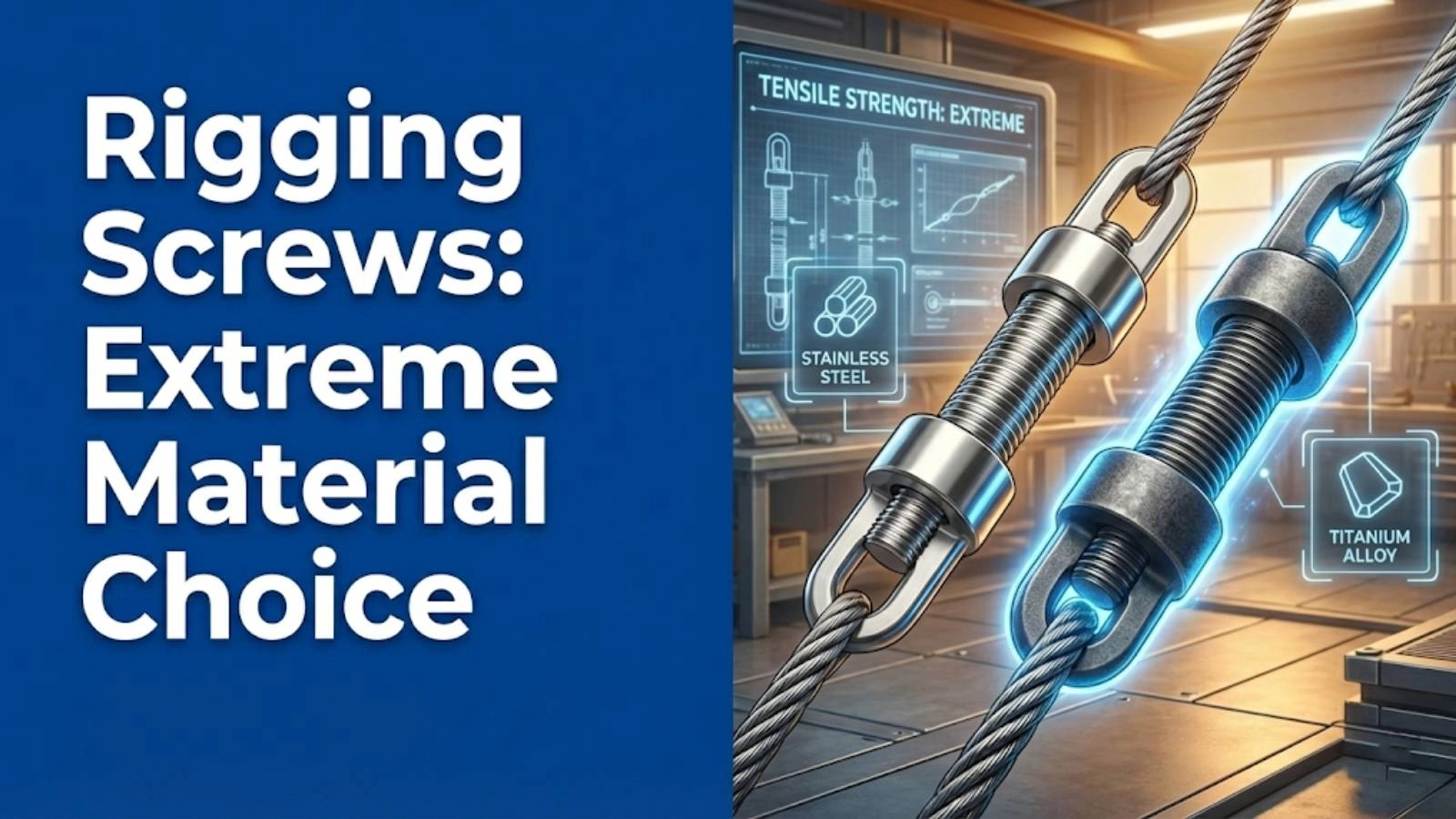
Choosing the right rigging screw material is crucial for safety and longevity. This guide highlights common mistakes in material selection and provides expert insights to ensure optimal performance in extreme environments.
Don't wait for disaster! Learn to identify the overlooked signs that indicate your rigging screw needs immediate replacement. Ensure operational safety and prevent costly failures.
Discover expert techniques for rigging screw maintenance. Extend the life of your rigging screws with our comprehensive guide, covering inspection, lubrication, and best practices. Learn how to prevent corrosion and ensure safe operation.
Learn how to prevent rigging screw failure and protect your equipment. This guide covers essential inspection, maintenance, and usage tips for beginners to avoid costly accidents and ensure safety.
Discover the common rigging screw mistakes that can compromise safety and efficiency. Learn from real-world examples and expert advice to prevent accidents and ensure secure operations.
This mode enables people with epilepsy to use the website safely by eliminating the risk of seizures that result from flashing or blinking animations and risky color combinations.
Visually Impaired Mode
Improves website's visuals
This mode adjusts the website for the convenience of users with visual impairments such as Degrading Eyesight, Tunnel Vision, Cataract, Glaucoma, and others.
Cognitive Disability Mode
Helps to focus on specific content
This mode provides different assistive options to help users with cognitive impairments such as Dyslexia, Autism, CVA, and others, to focus on the essential elements of the website more easily.
ADHD Friendly Mode
Reduces distractions and improve focus
This mode helps users with ADHD and Neurodevelopmental disorders to read, browse, and focus on the main website elements more easily while significantly reducing distractions.
Blindness Mode
Allows using the site with your screen-reader
This mode configures the website to be compatible with screen-readers such as JAWS, NVDA, VoiceOver, and TalkBack. A screen-reader is software for blind users that is installed on a computer and smartphone, and websites must be compatible with it.
Online Dictionary
Readable Experience
Content Scaling
Default
Text Magnifier
Readable Font
Dyslexia Friendly
Highlight Titles
Highlight Links
Font Sizing
Default
Line Height
Default
Letter Spacing
Default
Left Aligned
Center Aligned
Right Aligned
Visually Pleasing Experience
Dark Contrast
Light Contrast
Monochrome
High Contrast
High Saturation
Low Saturation
Adjust Text Colors
Adjust Title Colors
Adjust Background Colors
Easy Orientation
Mute Sounds
Hide Images
Hide Emoji
Reading Guide
Stop Animations
Reading Mask
Highlight Hover
Highlight Focus
Big Dark Cursor
Big Light Cursor
Cognitive Reading
Virtual Keyboard
Navigation Keys
Voice Navigation
Accessibility Statement
safeandsecureksa.com
5 April 2026
Compliance status
We firmly believe that the internet should be available and accessible to anyone, and are committed to providing a website that is accessible to the widest possible audience,
regardless of circumstance and ability.
To fulfill this, we aim to adhere as strictly as possible to the World Wide Web Consortium’s (W3C) Web Content Accessibility Guidelines 2.1 (WCAG 2.1) at the AA level.
These guidelines explain how to make web content accessible to people with a wide array of disabilities. Complying with those guidelines helps us ensure that the website is accessible
to all people: blind people, people with motor impairments, visual impairment, cognitive disabilities, and more.
This website utilizes various technologies that are meant to make it as accessible as possible at all times. We utilize an accessibility interface that allows persons with specific
disabilities to adjust the website’s UI (user interface) and design it to their personal needs.
Additionally, the website utilizes an AI-based application that runs in the background and optimizes its accessibility level constantly. This application remediates the website’s HTML,
adapts Its functionality and behavior for screen-readers used by the blind users, and for keyboard functions used by individuals with motor impairments.
If you’ve found a malfunction or have ideas for improvement, we’ll be happy to hear from you. You can reach out to the website’s operators by using the following email
Screen-reader and keyboard navigation
Our website implements the ARIA attributes (Accessible Rich Internet Applications) technique, alongside various different behavioral changes, to ensure blind users visiting with
screen-readers are able to read, comprehend, and enjoy the website’s functions. As soon as a user with a screen-reader enters your site, they immediately receive
a prompt to enter the Screen-Reader Profile so they can browse and operate your site effectively. Here’s how our website covers some of the most important screen-reader requirements,
alongside console screenshots of code examples:
Screen-reader optimization: we run a background process that learns the website’s components from top to bottom, to ensure ongoing compliance even when updating the website.
In this process, we provide screen-readers with meaningful data using the ARIA set of attributes. For example, we provide accurate form labels;
descriptions for actionable icons (social media icons, search icons, cart icons, etc.); validation guidance for form inputs; element roles such as buttons, menus, modal dialogues (popups),
and others. Additionally, the background process scans all the website’s images and provides an accurate and meaningful image-object-recognition-based description as an ALT (alternate text) tag
for images that are not described. It will also extract texts that are embedded within the image, using an OCR (optical character recognition) technology.
To turn on screen-reader adjustments at any time, users need only to press the Alt+1 keyboard combination. Screen-reader users also get automatic announcements to turn the Screen-reader mode on
as soon as they enter the website.
These adjustments are compatible with all popular screen readers, including JAWS and NVDA.
Keyboard navigation optimization: The background process also adjusts the website’s HTML, and adds various behaviors using JavaScript code to make the website operable by the keyboard. This includes the ability to navigate the website using the Tab and Shift+Tab keys, operate dropdowns with the arrow keys, close them with Esc, trigger buttons and links using the Enter key, navigate between radio and checkbox elements using the arrow keys, and fill them in with the Spacebar or Enter key.Additionally, keyboard users will find quick-navigation and content-skip menus, available at any time by clicking Alt+1, or as the first elements of the site while navigating with the keyboard. The background process also handles triggered popups by moving the keyboard focus towards them as soon as they appear, and not allow the focus drift outside it.
Users can also use shortcuts such as “M” (menus), “H” (headings), “F” (forms), “B” (buttons), and “G” (graphics) to jump to specific elements.
Disability profiles supported in our website
Epilepsy Safe Mode: this profile enables people with epilepsy to use the website safely by eliminating the risk of seizures that result from flashing or blinking animations and risky color combinations.
Visually Impaired Mode: this mode adjusts the website for the convenience of users with visual impairments such as Degrading Eyesight, Tunnel Vision, Cataract, Glaucoma, and others.
Cognitive Disability Mode: this mode provides different assistive options to help users with cognitive impairments such as Dyslexia, Autism, CVA, and others, to focus on the essential elements of the website more easily.
ADHD Friendly Mode: this mode helps users with ADHD and Neurodevelopmental disorders to read, browse, and focus on the main website elements more easily while significantly reducing distractions.
Blindness Mode: this mode configures the website to be compatible with screen-readers such as JAWS, NVDA, VoiceOver, and TalkBack. A screen-reader is software for blind users that is installed on a computer and smartphone, and websites must be compatible with it.
Keyboard Navigation Profile (Motor-Impaired): this profile enables motor-impaired persons to operate the website using the keyboard Tab, Shift+Tab, and the Enter keys. Users can also use shortcuts such as “M” (menus), “H” (headings), “F” (forms), “B” (buttons), and “G” (graphics) to jump to specific elements.
Additional UI, design, and readability adjustments
Font adjustments – users, can increase and decrease its size, change its family (type), adjust the spacing, alignment, line height, and more.
Color adjustments – users can select various color contrast profiles such as light, dark, inverted, and monochrome. Additionally, users can swap color schemes of titles, texts, and backgrounds, with over seven different coloring options.
Animations – person with epilepsy can stop all running animations with the click of a button. Animations controlled by the interface include videos, GIFs, and CSS flashing transitions.
Content highlighting – users can choose to emphasize important elements such as links and titles. They can also choose to highlight focused or hovered elements only.
Audio muting – users with hearing devices may experience headaches or other issues due to automatic audio playing. This option lets users mute the entire website instantly.
Cognitive disorders – we utilize a search engine that is linked to Wikipedia and Wiktionary, allowing people with cognitive disorders to decipher meanings of phrases, initials, slang, and others.
Additional functions – we provide users the option to change cursor color and size, use a printing mode, enable a virtual keyboard, and many other functions.
Browser and assistive technology compatibility
We aim to support the widest array of browsers and assistive technologies as possible, so our users can choose the best fitting tools for them, with as few limitations as possible. Therefore, we have worked very hard to be able to support all major systems that comprise over 95% of the user market share including Google Chrome, Mozilla Firefox, Apple Safari, Opera and Microsoft Edge, JAWS and NVDA (screen readers).
Notes, comments, and feedback
Despite our very best efforts to allow anybody to adjust the website to their needs. There may still be pages or sections that are not fully accessible, are in the process of becoming accessible, or are lacking an adequate technological solution to make them accessible. Still, we are continually improving our accessibility, adding, updating and improving its options and features, and developing and adopting new technologies. All this is meant to reach the optimal level of accessibility, following technological advancements. For any assistance, please reach out to