Unlock the secrets to spreader beam capacity! Learn how to maximize load limits, ensure safety, and optimize lifting operations with our comprehensive guide. Essential reading for engineers and safety professionals.
Spreader beams are essential tools in heavy lifting operations, providing stability and distributing loads evenly. Understanding spreader beam capacity is crucial for ensuring safety and efficiency on any job site. Safe and Secure Trading Company (SSTC) prioritizes educating our clients on the best practices for using lifting equipment, and this comprehensive guide will walk you through everything you need to know about spreader beam capacity, from fundamental principles to advanced design considerations.
Understanding Spreader Beam Fundamentals
Defining Spreader Beams and Their Purpose
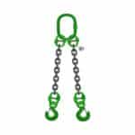
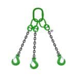
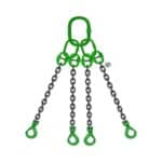
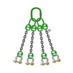
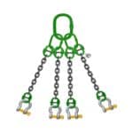
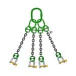
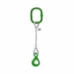
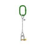
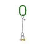
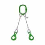
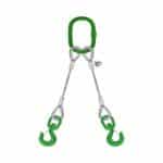
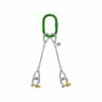
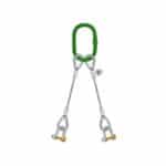
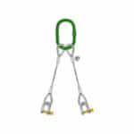
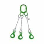
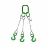
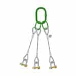
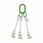
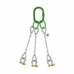
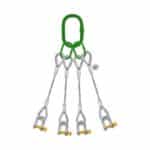
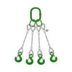
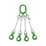
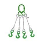
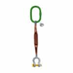
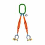
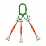
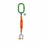
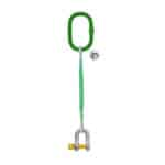
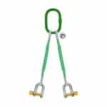
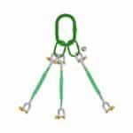
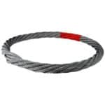
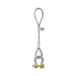
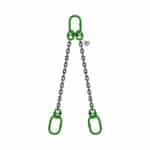
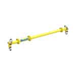
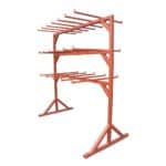
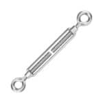
A spreader beam, also known as a lifting beam, is a below-the-hook lifting device designed to spread or distribute a load over two or more lifting points. Unlike a lifting beam, which primarily supports a load from a single point, a spreader beam is suspended between two or more slings, with the load suspended from one or more points along the beam. This configuration is particularly useful for handling long, flexible, or awkwardly shaped loads where stability and even weight distribution are paramount. Spreader beams are widely used in construction, manufacturing, and transportation industries to safely and efficiently lift and move heavy objects.
Spreader beams offer several advantages over other lifting methods. They reduce stress on the load by distributing weight evenly, minimize headroom requirements compared to using slings alone, and prevent crushing or damage to fragile loads. By maintaining a consistent distance between lifting points, spreader beams also enhance stability during lifts, reducing the risk of load sway or tipping. SSTC has seen countless projects benefit from the precise control and safety offered by well-designed spreader beam systems.
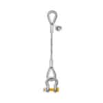
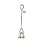
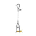
Key Components of a Spreader Beam System
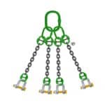
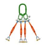
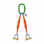
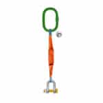
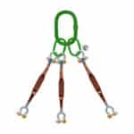
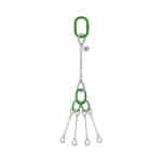
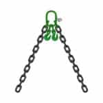
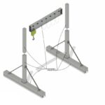
A typical spreader beam system consists of several key components that work together to ensure safe and effective lifting. These components include:
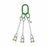
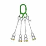
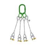
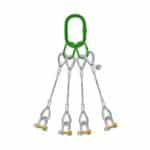
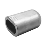
The Spreader Beam: The main structural element, typically made of steel, that distributes the load.
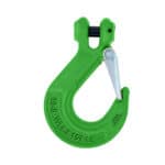
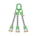
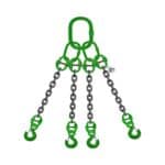
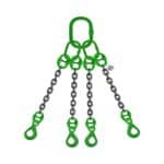
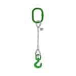
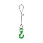
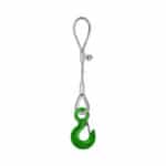
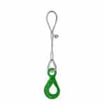
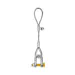
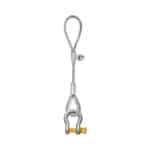
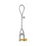
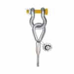
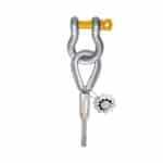
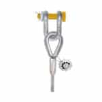
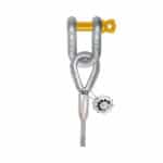
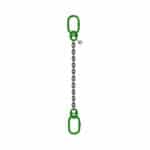
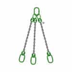
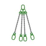
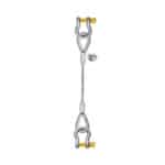
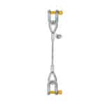
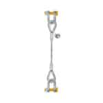
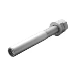
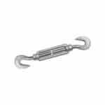
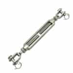
Top Rigging: This includes slings, shackles, and other hardware used to connect the spreader beam to the crane or lifting device.
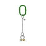
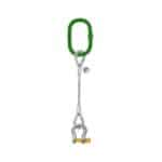
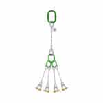
Load Slings: These connect the spreader beam to the load, providing multiple lifting points.
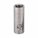
Shackles and Connectors: Used to connect the various components of the system securely.
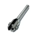
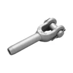
Lifting Points: These are the points on the spreader beam where the load slings are attached.
End Fittings: These are located at the ends of the spreader beam and connect to the top rigging.
[IMAGE: Diagram of a typical spreader beam system, labeling all key components.]
Each component plays a critical role in the overall performance and safety of the lifting operation. The spreader beam itself must be designed to withstand the anticipated loads, while the rigging and connectors must be properly sized and inspected to prevent failures. The lifting points should be positioned to ensure even load distribution and stability. Understanding the function and limitations of each component is essential for selecting and using spreader beams safely.
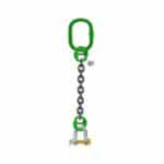
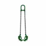
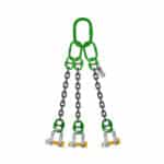
Types of Spreader Beams: Adjustable, Fixed, Telescopic
Spreader beams come in various designs to suit different lifting requirements. The three most common types are adjustable, fixed, and telescopic spreader beams.
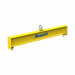
Fixed Spreader Beams: These have fixed lifting points and are suitable for repetitive lifting tasks involving loads of consistent size and shape. They are simple, reliable, and generally more cost-effective than adjustable or telescopic beams.
Adjustable Spreader Beams: These allow for the adjustment of lifting point positions, making them versatile for handling loads of varying dimensions. The adjustment can be achieved through sliding mechanisms, pin connections, or other methods. Adjustable spreader beams provide flexibility and adaptability for diverse lifting scenarios. When our team in Dubai needs to lift varying precast components, adjustable spreader beams are the first choice.
Telescopic Spreader Beams: These offer the greatest flexibility, with the ability to extend or retract the beam length to accommodate different load sizes and shapes. Telescopic beams are particularly useful for lifting long, slender objects or for navigating confined spaces.
The choice of spreader beam type depends on the specific application, load characteristics, and operational requirements. Fixed beams are ideal for repetitive tasks with consistent loads, while adjustable and telescopic beams offer greater versatility for handling diverse lifting scenarios.
Industry Standards and Regulations Governing Spreader Beams
The design, manufacturing, and use of spreader beams are governed by various industry standards and regulations to ensure safety and prevent accidents. These standards provide guidelines for material selection, design calculations, manufacturing processes, inspection procedures, and safe operating practices. Key standards include:
ASME B30.20: This standard covers below-the-hook lifting devices, including spreader beams, and provides requirements for design, construction, inspection, testing, and maintenance.
ANSI/ASME BTH-1: This standard provides guidelines for the design of below-the-hook lifting devices, including spreader beams, and covers topics such as load rating, stress analysis, and material selection.
OSHA Regulations: The Occupational Safety and Health Administration (OSHA) sets forth regulations for workplace safety, including requirements for the safe use of lifting equipment.
Compliance with these standards and regulations is essential for ensuring the safety and reliability of spreader beam systems. Manufacturers must adhere to design and manufacturing standards, while users must follow safe operating practices and inspection procedures. Regular training and competency assessments are also crucial for personnel involved in lifting operations. Ignoring these standards can lead to catastrophic failures and serious injuries.
Calculating Spreader Beam Capacity: A Detailed Approach
Load Weight Estimation and Considerations
Accurate load weight estimation is the first and most critical step in determining the appropriate spreader beam capacity. Underestimating the load weight can lead to overloading, which can cause the spreader beam to fail, resulting in property damage, injuries, or fatalities. To ensure accurate load weight estimation, consider the following:
Obtain Accurate Weight Data: Consult the manufacturer’s specifications, shipping documents, or other reliable sources to determine the weight of the load.
Account for Additional Weight: Consider any additional weight that may be added to the load, such as rigging, packaging, or temporary supports.
Use a Calibrated Weighing System: If the weight data is not readily available, use a calibrated weighing system, such as a crane scale or load cell, to measure the weight of the load accurately.
It’s always better to overestimate the load weight slightly to provide a margin of safety. Remember, the spreader beam capacity must be sufficient to handle the maximum anticipated load weight, including any additional weight or dynamic loads.
Determining the Center of Gravity (CG) of the Load
The center of gravity (CG) of the load is the point at which the entire weight of the load is concentrated. Determining the CG is essential for ensuring stable and balanced lifting. An incorrectly positioned CG can cause the load to tilt, sway, or even tip over during lifting, leading to accidents and injuries. To determine the CG of the load, consider the following:
Symmetrical Loads: For symmetrical loads, the CG is typically located at the geometric center of the load.
Asymmetrical Loads: For asymmetrical loads, the CG must be determined through calculations or experiments. One common method is to suspend the load from two different points and measure the angles of the suspension lines. The intersection of the vertical lines from these suspension points indicates the CG.
Complex Loads: For complex loads with multiple components, the CG can be determined by calculating the weighted average of the CGs of each component.
[IMAGE: Diagram illustrating how to find the center of gravity of an asymmetrical load.]
Accurate determination of the CG is crucial for proper rigging and load balancing. The lifting points on the spreader beam should be positioned to ensure that the CG is directly below the lifting point, preventing tilting or instability during lifting.
Understanding Load Distribution on the Spreader Beam
The load distribution on the spreader beam depends on the location of the lifting points and the CG of the load. Understanding how the load is distributed is essential for calculating the bending moment and shear force on the beam. The following factors affect load distribution:
Lifting Point Locations: The position of the lifting points on the spreader beam directly affects the load distribution. Lifting points closer to the center of the beam result in a more even load distribution, while lifting points closer to the ends of the beam concentrate the load at those points.
CG Location: The location of the CG of the load relative to the lifting points also affects load distribution. If the CG is directly below a lifting point, that point will bear a larger portion of the load.
Sling Angles: The angles of the slings connecting the spreader beam to the load also influence load distribution. Steeper sling angles increase the tension in the slings and the load on the lifting points.
To ensure proper load distribution, the lifting points should be positioned to balance the load and minimize bending moments and shear forces on the spreader beam.
Calculating Bending Moment and Shear Force
The bending moment and shear force are critical parameters for assessing the structural integrity of the spreader beam. The bending moment is a measure of the internal forces that resist bending, while the shear force is a measure of the internal forces that resist shearing. These forces must be calculated to ensure that the spreader beam capacity is not exceeded. The following steps are involved in calculating bending moment and shear force:
1. Determine the Load Distribution: Calculate the load acting at each lifting point based on the load weight, CG location, and sling angles.
2. Calculate the Shear Force: Determine the shear force at various points along the beam by summing the vertical forces acting on one side of the point.
3. Calculate the Bending Moment: Determine the bending moment at various points along the beam by summing the moments of the forces acting on one side of the point.
The maximum bending moment and shear force typically occur at the center of the beam or at the lifting points. These values must be compared to the allowable bending moment and shear force for the beam material to ensure that the beam can safely withstand the applied loads.
Here’s a sample table demonstrating the relationship between load, distance, shear force, and bending moment for a simple spreader beam configuration.
Parameter
Description
Formula
Load (W)
Total weight being lifted
W (in Newtons or lbs)
Distance (L)
Length of the spreader beam
L (in meters or feet)
Shear Force (V)
Internal force acting perpendicular to the beam’s axis
V = W/2 (at supports)
Bending Moment (M)
Internal force causing the beam to bend
M = (W * L) / 4 (at center)
Stress Analysis and Material Selection
Stress analysis is a crucial step in verifying the structural integrity of the spreader beam. It involves determining the stresses induced in the beam material due to the applied loads. The calculated stresses must be compared to the allowable stresses for the material to ensure that the beam can safely withstand the loads without yielding or fracturing. The following factors are considered in stress analysis:
Tensile Stress: Stress caused by tension or pulling forces.
Compressive Stress: Stress caused by compression or pushing forces.
Shear Stress: Stress caused by forces acting parallel to the beam’s surface.
Bending Stress: Stress caused by bending moments.
The material selection for the spreader beam is based on its strength, weight, corrosion resistance, and cost. Common materials include:
Carbon Steel: A cost-effective and widely used material for spreader beams.
Alloy Steel: Offers higher strength and toughness compared to carbon steel.
High-Strength Low-Alloy (HSLA) Steel: Provides a good balance of strength, weldability, and corrosion resistance.
The selected material must have sufficient strength and ductility to withstand the anticipated stresses and strains without failure.
Safety Factors: Applying Appropriate Margins
Safety factors are applied to the calculated stresses to provide a margin of safety and account for uncertainties in load estimation, material properties, and manufacturing processes. A safety factor is a multiplier that is applied to the allowable stress or the calculated stress to ensure that the beam can safely withstand the applied loads. The appropriate safety factor depends on the application, industry standards, and regulatory requirements. Typical safety factors for spreader beams range from 2 to 5.
> “When designing spreader beams, always err on the side of caution. A higher safety factor might increase the initial cost, but it significantly reduces the risk of catastrophic failure and ensures the safety of everyone involved.” – John Smith, Senior Structural Engineer at SSTC
Applying appropriate safety factors is crucial for ensuring the long-term reliability and safety of spreader beam systems.
Factors Affecting Spreader Beam Capacity
Material Properties: Steel Grades and Alloys
The material properties of the steel used in a spreader beam significantly impact its spreader beam capacity. Different steel grades and alloys offer varying levels of strength, ductility, and weldability, which directly influence the beam’s ability to withstand applied loads. High-strength steels, such as alloy steels and HSLA steels, allow for lighter and more compact designs while maintaining adequate load-bearing capacity. However, the selection of steel grade must also consider other factors, such as cost, availability, and corrosion resistance. Here’s a table that shows some common steel grades:
Steel Grade
Tensile Strength (MPa)
Yield Strength (MPa)
Applications
A36 Carbon Steel
400-550
250
General construction, basic spreader beams
A572 HSLA Steel
415-550
345
Higher strength applications, lighter designs
A514 Alloy Steel
690-830
620
Heavy-duty lifting, critical applications
Beam Geometry: Length, Height, and Flange Thickness
The geometry of the spreader beam, including its length, height, and flange thickness, plays a crucial role in determining its spreader beam capacity. Longer beams are more susceptible to bending and deflection, while shorter beams offer greater stiffness and load-bearing capacity. Increasing the height of the beam increases its resistance to bending, while increasing the flange thickness enhances its resistance to buckling. Optimizing the beam geometry is essential for maximizing its load capacity while minimizing its weight and cost. Finite element analysis (FEA) is often used to optimize beam geometry for specific loading conditions.
Welding Quality and Inspection Procedures
Welding is a critical process in the fabrication of spreader beams, and the quality of the welds directly affects the beam’s structural integrity and spreader beam capacity. Poor welding practices can introduce defects, such as cracks, porosity, and incomplete fusion, which can significantly reduce the beam’s strength and lead to premature failure. Proper welding procedures, qualified welders, and thorough inspection are essential for ensuring the quality and reliability of welded connections. Non-destructive testing (NDT) methods, such as ultrasonic testing and magnetic particle inspection, are used to detect weld defects and verify the integrity of welded joints.
Environmental Conditions: Temperature and Corrosion
Environmental conditions, such as temperature and corrosion, can significantly affect the spreader beam capacity and service life. Extreme temperatures can alter the material properties of the steel, reducing its strength and ductility. Corrosion can weaken the beam by reducing its cross-sectional area and introducing stress concentrations. Regular inspection and maintenance are essential for detecting and mitigating the effects of environmental factors. Protective coatings, such as paint or galvanizing, can be applied to prevent corrosion. In harsh environments, such as offshore oil and gas operations, special materials and coatings may be required to ensure long-term durability.
Dynamic Loading Considerations: Impact and Vibration
Dynamic loads, such as impact and vibration, can significantly increase the stresses on the spreader beam and reduce its effective spreader beam capacity. Impact loads occur when the load is suddenly applied or dropped, while vibration loads occur due to oscillating forces. These dynamic loads can induce stress concentrations and fatigue, which can lead to premature failure. To account for dynamic loads, a dynamic load factor is applied to the static load when calculating the required spreader beam capacity. The dynamic load factor depends on the severity of the impact or vibration and the damping characteristics of the system.
Maximizing Spreader Beam Capacity Safely
Proper Rigging Techniques and Practices
Proper rigging techniques are essential for maximizing the spreader beam capacity safely. Incorrect rigging can lead to uneven load distribution, excessive stress on the beam, and instability during lifting. Key rigging practices include:
Using Correct Sling Angles: Sling angles should be minimized to reduce tension in the slings and the load on the lifting points.
Ensuring Proper Sling Lengths: Sling lengths should be adjusted to ensure even load distribution and prevent overloading of individual slings.
Using Appropriate Shackles and Connectors: Shackles and connectors should be properly sized and rated for the anticipated loads.
Avoiding Sharp Bends and Kinks: Slings should be protected from sharp bends and kinks, which can reduce their strength.
Regular inspection of rigging hardware is also crucial for detecting wear, damage, or corrosion.
Load Balancing and Distribution Strategies
Effective load balancing and distribution are critical for maximizing the spreader beam capacity and ensuring stable lifting. Uneven load distribution can overload one side of the beam, leading to excessive stress and potential failure. Strategies for load balancing include:
Positioning Lifting Points Correctly: The lifting points should be positioned to ensure that the CG of the load is directly below the lifting point.
Using Adjustable Slings: Adjustable slings can be used to fine-tune the load distribution and compensate for variations in load weight or geometry.
Using Load Cells: Load cells can be used to monitor the load distribution in real-time and make adjustments as needed.
By carefully balancing the load and distributing it evenly across the spreader beam, you can maximize its capacity and minimize the risk of accidents.
Regular Inspection and Maintenance Procedures
Regular inspection and maintenance are essential for ensuring the long-term reliability and safety of spreader beams. Inspections should be conducted before each use to detect any signs of damage, wear, or corrosion. Maintenance procedures should include:
Cleaning: Removing dirt, debris, and corrosion from the beam surface.
Lubrication: Lubricating moving parts, such as adjustment mechanisms and pin connections.
Repair: Repairing or replacing damaged components, such as slings, shackles, and connectors.
Load Testing: Periodically load testing the beam to verify its spreader beam capacity and structural integrity.
A documented inspection and maintenance program is crucial for tracking the condition of the spreader beam and ensuring that it is safe to use.
Training and Competency of Personnel
Proper training and competency of personnel are essential for the safe and effective use of spreader beams. Personnel involved in lifting operations should be trained in:
Spreader Beam Operation: Understanding the principles of operation, load limitations, and safety procedures.
Rigging Techniques: Proper rigging practices, sling angles, and load balancing.
Inspection Procedures: Identifying signs of damage, wear, or corrosion.
Emergency Procedures: Responding to emergencies, such as load instability or equipment failure.
Regular competency assessments should be conducted to ensure that personnel maintain the required skills and knowledge. SSTC prioritizes comprehensive training programs to ensure that all personnel involved in lifting operations are fully competent and aware of safety procedures.
Using Load Monitoring Systems
Load monitoring systems provide real-time data on the load weight, distribution, and stress levels on the spreader beam. These systems can help prevent overloading, detect uneven load distribution, and identify potential problems before they lead to accidents. Load monitoring systems typically consist of:
Load Cells: Sensors that measure the force applied to the beam.
Data Acquisition System: A system that collects and processes the data from the load cells.
Display Unit: A display unit that shows the load weight, distribution, and stress levels.
Load monitoring systems can be integrated with alarm systems that alert operators when load limits are exceeded or when abnormal conditions are detected.
Spreader Beam Design Considerations
Finite Element Analysis (FEA) for Design Optimization
Finite Element Analysis (FEA) is a powerful computer-based simulation technique used to analyze the structural behavior of spreader beams under various loading conditions. FEA allows engineers to optimize the beam design, predict stress distributions, and identify potential failure points. By simulating real-world scenarios, FEA helps ensure that the spreader beam meets the required spreader beam capacity and safety standards. FEA is particularly useful for complex beam geometries and loading conditions where traditional calculation methods may be insufficient.
Optimizing Beam Geometry for Maximum Load Capacity
Optimizing the beam geometry is crucial for maximizing the spreader beam capacity while minimizing its weight and cost. The optimal beam geometry depends on the specific loading conditions, material properties, and design constraints. Key geometric parameters to optimize include:
Beam Height: Increasing the beam height increases its resistance to bending.
Flange Thickness: Increasing the flange thickness enhances its resistance to buckling.
Web Thickness: Increasing the web thickness enhances its resistance to shear.
Beam Length: Shorter beams offer greater stiffness and load-bearing capacity.
FEA can be used to evaluate different beam geometries and identify the optimal configuration for a given application.
Selecting the Appropriate Connection Methods
The connection methods used to join the various components of the spreader beam are critical for its structural integrity and spreader beam capacity. Common connection methods include:
Welding: A widely used method for joining steel components.
Bolting: A method that uses bolts to fasten components together.
Pin Connections: A method that uses pins to connect components.
The selection of the appropriate connection method depends on the load requirements, material properties, and manufacturing capabilities. Welded connections offer high strength and rigidity, while bolted connections offer ease of assembly and disassembly. Pin connections are often used for adjustable or articulating joints. The connection method must be designed to withstand the anticipated loads and prevent premature failure.
Designing for Stability and Preventing Buckling
Stability is a critical consideration in spreader beam design. The beam must be designed to prevent buckling, which is a sudden and catastrophic failure mode that occurs when a slender structural member is subjected to compressive loads. Buckling can occur in the beam flanges, web, or columns. To prevent buckling, the following measures can be taken:
Increasing Flange Thickness: Increasing the flange thickness enhances its resistance to buckling.
Adding Stiffeners: Adding stiffeners to the web or flanges can increase their resistance to buckling.
Reducing Beam Length: Shorter beams are less susceptible to buckling.
Using Higher Strength Materials: Higher strength materials offer greater resistance to buckling.
FEA can be used to analyze the stability of the spreader beam and identify potential buckling modes.
Regular visual inspections are crucial for identifying potential problems with the spreader beam before they lead to accidents. A thorough visual inspection should include checking for:
Cracks: Look for cracks in the welds, base metal, and connection points.
Deformations: Check for bending, twisting, or buckling of the beam.
Corrosion: Inspect for rust, pitting, or other signs of corrosion.
Wear: Look for wear on slings, shackles, and connectors.
Loose Connections: Check for loose bolts, pins, or other fasteners.
Any signs of damage or deterioration should be investigated and addressed immediately.
Non-Destructive Testing (NDT) Methods: Ultrasonic Testing, Magnetic Particle Inspection
Non-Destructive Testing (NDT) methods are used to detect internal defects in the spreader beam without damaging the material. Common NDT methods include:
Ultrasonic Testing (UT): Uses sound waves to detect cracks, voids, and other internal defects.
Magnetic Particle Inspection (MPI): Uses magnetic fields to detect surface and near-surface cracks.
Radiographic Testing (RT): Uses X-rays or gamma rays to detect internal defects.
Dye Penetrant Inspection (DPI): Uses a dye to detect surface cracks.
NDT methods should be performed by qualified personnel and in accordance with industry standards.
Load Testing Procedures and Frequency
Load testing is a critical step in verifying the spreader beam capacity and structural integrity. Load testing involves applying a known load to the beam and measuring its deflection and stress levels. The load test should be performed:
After Manufacturing: To verify that the beam meets the design requirements.
After Repairs: To verify that the repairs have restored the beam to its original strength.
Periodically: To detect any degradation in the beam’s performance over time.
The load test should be performed in accordance with industry standards and under the supervision of a qualified engineer.
Repair and Replacement Criteria
Repair or replacement of the spreader beam is necessary when it exhibits signs of:
Cracks: Cracks in critical areas of the beam.
Excessive Deformation: Bending, twisting, or buckling beyond allowable limits.
Severe Corrosion: Significant loss of material due to corrosion.
Weld Defects: Unacceptable weld defects detected during NDT.
Failure to Pass Load Test: Failure to meet the required performance criteria during load testing.
Repairs should be performed by qualified welders and engineers and should be followed by load testing to verify the effectiveness of the repairs. If the damage is too severe or the repairs are not feasible, the spreader beam should be replaced.
Common Mistakes to Avoid When Using Spreader Beams
Overloading the Spreader Beam
Overloading is one of the most common and dangerous mistakes when using spreader beams. Overloading can cause the beam to fail, resulting in property damage, injuries, or fatalities. To avoid overloading:
Accurately Estimate Load Weight: Use reliable sources to determine the weight of the load.
Consider Additional Weight: Account for any additional weight, such as rigging or packaging.
Do Not Exceed Rated Capacity: Never exceed the rated spreader beam capacity.
Use Load Monitoring Systems: Monitor the load weight in real-time to prevent overloading.
Improper Rigging and Sling Angles
Improper rigging and sling angles can significantly reduce the effective spreader beam capacity and increase the risk of accidents. Common rigging mistakes include:
Excessive Sling Angles: Using sling angles that are too steep, which increases tension in the slings.
Uneven Sling Lengths: Using slings of unequal length, which can cause uneven load distribution.
Sharp Bends and Kinks: Allowing slings to bend sharply or kink, which reduces their strength.
Incorrect Sling Attachment: Attaching slings to the load in a way that creates stress concentrations.
Neglecting Load Balancing
Neglecting load balancing can lead to uneven load distribution and excessive stress on one side of the spreader beam. To avoid neglecting load balancing:
Determine the Center of Gravity: Accurately determine the CG of the load.
Position Lifting Points Correctly: Position the lifting points to ensure that the CG is directly below the lifting point.
Use Adjustable Slings: Use adjustable slings to fine-tune the load distribution.
Monitor Load Distribution: Use load cells to monitor the load distribution in real-time.
Ignoring Environmental Factors
Ignoring environmental factors, such as temperature and corrosion, can lead to premature failure of the spreader beam. To avoid ignoring environmental factors:
Use Appropriate Materials: Select materials that are resistant to corrosion and temperature extremes.
Apply Protective Coatings: Apply protective coatings, such as paint or galvanizing, to prevent corrosion.
Regularly Inspect for Corrosion: Regularly inspect the beam for signs of corrosion.
Adjust Load Capacity for Temperature: Reduce the spreader beam capacity in extreme temperatures.
Lack of Regular Inspection and Maintenance
Lack of regular inspection and maintenance can allow minor problems to escalate into major failures. To avoid this:
Establish a Regular Inspection Program: Develop a documented inspection program that includes visual inspections and NDT methods.
Perform Routine Maintenance: Perform routine maintenance, such as cleaning, lubrication, and repair of damaged components.
Keep Records of Inspections and Maintenance: Maintain records of all inspections and maintenance activities.
Follow Manufacturer’s Recommendations: Follow the manufacturer’s recommendations for inspection and maintenance.
Case Studies: Real-World Spreader Beam Applications
Lifting Large Bridge Sections
Spreader beams are commonly used in the construction of bridges to lift and position large bridge sections. These sections can weigh hundreds of tons and require precise control and stability during lifting. Spreader beams distribute the load evenly across multiple lifting points, minimizing stress on the bridge section and preventing damage. The use of adjustable spreader beams allows for flexibility in accommodating different bridge section sizes and shapes.
Moving Heavy Machinery in Industrial Plants
In industrial plants, spreader beams are used to move heavy machinery, such as generators, turbines, and presses. These machines often weigh several tons and require specialized lifting equipment. Spreader beams provide the necessary stability and load distribution to safely move these machines within the plant. The use of telescopic spreader beams allows for maneuvering in confined spaces and around obstacles.
Offshore Oil and Gas Operations
Offshore oil and gas operations involve the lifting and installation of heavy equipment, such as drilling modules, subsea structures, and pipelines. Spreader beams are essential for these operations, providing the necessary load capacity and stability in harsh marine environments. The use of specialized materials and coatings ensures that the spreader beams can withstand the corrosive effects of seawater and the extreme conditions of offshore operations.
Wind Turbine Installation
Wind turbine installation involves the lifting and assembly of large turbine components, such as blades, nacelles, and tower sections. Spreader beams are used to lift these components to great heights and position them accurately. The use of load monitoring systems helps ensure that the loads are within the spreader beam capacity and that the lifting operation is performed safely. Wind turbine installations often require specialized spreader beams designed for the unique challenges of lifting these large and complex components.
Troubleshooting Spreader Beam Capacity Issues
Identifying the Root Cause of Capacity Limitations
When encountering spreader beam capacity issues, identifying the root cause is crucial for implementing effective corrective actions. Common causes of capacity limitations include:
Incorrect Load Weight Estimation: Underestimating the load weight can lead to overloading.
Improper Rigging: Incorrect rigging can reduce the effective spreader beam capacity.
Material Degradation: Corrosion, wear, or fatigue can weaken the beam.
Design Flaws: Design flaws can limit the beam’s capacity.
Environmental Factors: Extreme temperatures or corrosive environments can reduce the beam’s capacity.
A thorough inspection and analysis are necessary to identify the root cause of the capacity limitations.
Implementing Corrective Actions to Improve Capacity
Once the root cause of the capacity limitations has been identified, corrective actions can be implemented to improve the spreader beam capacity. These actions may include:
Re-estimating Load Weight: Accurately re-estimating the load weight using reliable sources.
Improving Rigging Techniques: Implementing proper rigging practices to maximize the effective spreader beam capacity.
Repairing or Replacing Damaged Components: Repairing or replacing damaged components, such as slings, shackles, or the beam itself.
Modifying the Beam Design: Modifying the beam design to increase its capacity.
Addressing Environmental Factors: Implementing measures to mitigate the effects of environmental factors, such as corrosion protection or temperature control.
Modifying the Spreader Beam Design for Increased Capacity
In some cases, it may be necessary to modify the spreader beam design to increase its capacity. Design modifications may include:
Increasing Beam Height: Increasing the beam height increases its resistance to bending.
Increasing Flange Thickness: Increasing the flange thickness enhances its resistance to buckling.
Adding Stiffeners: Adding stiffeners to the web or flanges can increase their resistance to buckling.
Using Higher Strength Materials: Using higher strength materials allows for a lighter and stronger design.
Any design modifications should be performed by qualified engineers and followed by load testing to verify the increased capacity.
Seeking Expert Consultation and Support
When facing complex spreader beam capacity issues, seeking expert consultation and support is highly recommended. Experienced engineers and lifting specialists can provide valuable insights and guidance to help identify the root cause of the problems and implement effective solutions. Expert consultation can also help ensure that the spreader beam design meets the required safety standards and regulations. SSTC offers expert consultation and support services to help our clients optimize their lifting operations and ensure safety.
The Future of Spreader Beam Technology
Advanced Materials and Design Techniques
The future of spreader beam technology will likely involve the use of advanced materials and design techniques to create lighter, stronger, and more efficient lifting equipment. Advanced materials, such as composite materials and high-strength alloys, offer the potential to significantly reduce the weight of spreader beams while maintaining or even increasing their spreader beam capacity. Advanced design techniques, such as topology optimization and additive manufacturing, can be used to create complex beam geometries that maximize load capacity while minimizing material usage.
Smart Spreader Beams with Integrated Sensors
Smart spreader beams with integrated sensors offer the potential to revolutionize lifting operations by providing real-time data on the load weight, distribution, stress levels, and environmental conditions. These sensors can be integrated with wireless communication systems to transmit data to a central monitoring station, allowing operators to monitor the lifting operation remotely. Smart spreader beams can also be equipped with alarm systems that alert operators when load limits are exceeded or when abnormal conditions are detected.
Automation and Robotics in Lifting Operations
Automation and robotics are increasingly being used in lifting operations to improve efficiency, safety, and precision. Robotic lifting systems can be programmed to perform repetitive lifting tasks with high accuracy and consistency. Automated spreader beam systems can be equipped with sensors and control systems to automatically adjust the lifting points and balance the load. The use of automation and robotics can significantly reduce the risk of human error and improve the overall safety of lifting operations.
Sustainability Considerations in Spreader Beam Manufacturing
Sustainability is becoming an increasingly important consideration in all industries, including the lifting equipment industry. Sustainable spreader beam manufacturing involves using environmentally friendly materials, reducing energy consumption, and minimizing waste. The use of recycled materials and the implementation of energy-efficient manufacturing processes can help reduce the environmental impact of spreader beam manufacturing. Designing spreader beams for durability and longevity can also help reduce the need for frequent replacement, further minimizing the environmental impact.
Conclusion
Understanding spreader beam capacity is paramount for ensuring safe and efficient lifting operations. We’ve explored the fundamentals, calculation methods, influencing factors, and best practices for maximizing spreader beam capacity safely. We’ve also covered inspection, maintenance, and troubleshooting techniques, along with a glimpse into the future of spreader beam technology. By adhering to these guidelines, you can confidently and safely handle even the most challenging lifting tasks. We are here to support your projects every step of the way!
Q: What is the primary purpose of a spreader beam?
A: The primary purpose of a spreader beam is to distribute a load evenly over two or more lifting points, providing stability and preventing damage to the load. It’s a below-the-hook lifting device designed to handle long, flexible, or awkwardly shaped loads.
Q: How do I determine the correct spreader beam capacity for my lifting operation?
A: To determine the correct spreader beam capacity, you need to accurately estimate the load weight, determine the center of gravity of the load, understand the load distribution on the beam, and apply appropriate safety factors. Always consult with qualified engineers and lifting specialists for complex lifting scenarios.
Q: What are some common mistakes to avoid when using spreader beams?
A: Common mistakes to avoid include overloading the spreader beam, improper rigging and sling angles, neglecting load balancing, ignoring environmental factors, and lack of regular inspection and maintenance. These mistakes can lead to accidents and equipment failure.
Q: How often should I inspect my spreader beam?
A: You should inspect your spreader beam before each use and periodically, as recommended by the manufacturer and industry standards. Regular inspections should include visual checks for cracks, deformations, corrosion, and wear.
Q: What are Non-Destructive Testing (NDT) methods, and when should they be used?
A: Non-Destructive Testing (NDT) methods are used to detect internal defects in the spreader beam without damaging the material. Common NDT methods include Ultrasonic Testing (UT), Magnetic Particle Inspection (MPI), Radiographic Testing (RT), and Dye Penetrant Inspection (DPI). These methods should be used periodically, especially after repairs or when visual inspections reveal potential issues.
Q: What should I do if I suspect that my spreader beam is overloaded?
A: If you suspect that your spreader beam is overloaded, immediately stop the lifting operation and lower the load safely. Re-evaluate the load weight and rigging setup, and ensure that the load does not exceed the rated spreader beam capacity. If necessary, consult with a qualified engineer or lifting specialist.
Q: Can I modify my spreader beam to increase its capacity?
A: Modifying a spreader beam to increase its capacity should only be done by qualified engineers and in accordance with industry standards. Design modifications may include increasing beam height, flange thickness, adding stiffeners, or using higher strength materials. Any modifications should be followed by load testing to verify the increased capacity.
Q: What are the key industry standards and regulations governing the use of spreader beams?
A: Key industry standards and regulations include
Related Tags: Crane Safety, Engineering, heavy lifting, Lifting Equipment, Load Capacity, Rigging, spreader beams
Choosing between a spreader beam and a lifting bar can be tricky. This guide helps you understand the pros and cons of each, ensuring safer and more efficient lifting operations. Make the right choice for your specific lifting needs.
Discover how spreader beams drastically improve lifting safety. Learn about load distribution, stability, and reduced stress, leading to fewer accidents and safer operations. Enhance your worksite with these essential safety measures.
Ensure spreader bar safety by avoiding common pitfalls. Learn how to prevent accidents, maintain equipment, and follow best practices for secure lifting operations. Protect your team and your assets with our expert advice.
Explore the latest lifting bar innovations transforming workouts. Discover upgrades that enhance safety, boost performance, and redefine your lifting experience. Stay ahead of the curve!
Navigate the complexities of spreader beam acquisition. This guide highlights common errors buyers make and provides actionable strategies for selecting the right spreader beam, ensuring safety, and optimizing your lifting operations.
Choosing between a spreader beam and a lifting bar can be confusing. This guide clarifies the differences, pros, and cons to help you make the right decision for safe and efficient lifting. Learn which option suits your specific needs.
This mode enables people with epilepsy to use the website safely by eliminating the risk of seizures that result from flashing or blinking animations and risky color combinations.
Visually Impaired Mode
Improves website's visuals
This mode adjusts the website for the convenience of users with visual impairments such as Degrading Eyesight, Tunnel Vision, Cataract, Glaucoma, and others.
Cognitive Disability Mode
Helps to focus on specific content
This mode provides different assistive options to help users with cognitive impairments such as Dyslexia, Autism, CVA, and others, to focus on the essential elements of the website more easily.
ADHD Friendly Mode
Reduces distractions and improve focus
This mode helps users with ADHD and Neurodevelopmental disorders to read, browse, and focus on the main website elements more easily while significantly reducing distractions.
Blindness Mode
Allows using the site with your screen-reader
This mode configures the website to be compatible with screen-readers such as JAWS, NVDA, VoiceOver, and TalkBack. A screen-reader is software for blind users that is installed on a computer and smartphone, and websites must be compatible with it.
Online Dictionary
Readable Experience
Content Scaling
Default
Text Magnifier
Readable Font
Dyslexia Friendly
Highlight Titles
Highlight Links
Font Sizing
Default
Line Height
Default
Letter Spacing
Default
Left Aligned
Center Aligned
Right Aligned
Visually Pleasing Experience
Dark Contrast
Light Contrast
Monochrome
High Contrast
High Saturation
Low Saturation
Adjust Text Colors
Adjust Title Colors
Adjust Background Colors
Easy Orientation
Mute Sounds
Hide Images
Hide Emoji
Reading Guide
Stop Animations
Reading Mask
Highlight Hover
Highlight Focus
Big Dark Cursor
Big Light Cursor
Cognitive Reading
Virtual Keyboard
Navigation Keys
Voice Navigation
Accessibility Statement
safeandsecureksa.com
14 March 2026
Compliance status
We firmly believe that the internet should be available and accessible to anyone, and are committed to providing a website that is accessible to the widest possible audience,
regardless of circumstance and ability.
To fulfill this, we aim to adhere as strictly as possible to the World Wide Web Consortium’s (W3C) Web Content Accessibility Guidelines 2.1 (WCAG 2.1) at the AA level.
These guidelines explain how to make web content accessible to people with a wide array of disabilities. Complying with those guidelines helps us ensure that the website is accessible
to all people: blind people, people with motor impairments, visual impairment, cognitive disabilities, and more.
This website utilizes various technologies that are meant to make it as accessible as possible at all times. We utilize an accessibility interface that allows persons with specific
disabilities to adjust the website’s UI (user interface) and design it to their personal needs.
Additionally, the website utilizes an AI-based application that runs in the background and optimizes its accessibility level constantly. This application remediates the website’s HTML,
adapts Its functionality and behavior for screen-readers used by the blind users, and for keyboard functions used by individuals with motor impairments.
If you’ve found a malfunction or have ideas for improvement, we’ll be happy to hear from you. You can reach out to the website’s operators by using the following email
Screen-reader and keyboard navigation
Our website implements the ARIA attributes (Accessible Rich Internet Applications) technique, alongside various different behavioral changes, to ensure blind users visiting with
screen-readers are able to read, comprehend, and enjoy the website’s functions. As soon as a user with a screen-reader enters your site, they immediately receive
a prompt to enter the Screen-Reader Profile so they can browse and operate your site effectively. Here’s how our website covers some of the most important screen-reader requirements,
alongside console screenshots of code examples:
Screen-reader optimization: we run a background process that learns the website’s components from top to bottom, to ensure ongoing compliance even when updating the website.
In this process, we provide screen-readers with meaningful data using the ARIA set of attributes. For example, we provide accurate form labels;
descriptions for actionable icons (social media icons, search icons, cart icons, etc.); validation guidance for form inputs; element roles such as buttons, menus, modal dialogues (popups),
and others. Additionally, the background process scans all the website’s images and provides an accurate and meaningful image-object-recognition-based description as an ALT (alternate text) tag
for images that are not described. It will also extract texts that are embedded within the image, using an OCR (optical character recognition) technology.
To turn on screen-reader adjustments at any time, users need only to press the Alt+1 keyboard combination. Screen-reader users also get automatic announcements to turn the Screen-reader mode on
as soon as they enter the website.
These adjustments are compatible with all popular screen readers, including JAWS and NVDA.
Keyboard navigation optimization: The background process also adjusts the website’s HTML, and adds various behaviors using JavaScript code to make the website operable by the keyboard. This includes the ability to navigate the website using the Tab and Shift+Tab keys, operate dropdowns with the arrow keys, close them with Esc, trigger buttons and links using the Enter key, navigate between radio and checkbox elements using the arrow keys, and fill them in with the Spacebar or Enter key.Additionally, keyboard users will find quick-navigation and content-skip menus, available at any time by clicking Alt+1, or as the first elements of the site while navigating with the keyboard. The background process also handles triggered popups by moving the keyboard focus towards them as soon as they appear, and not allow the focus drift outside it.
Users can also use shortcuts such as “M” (menus), “H” (headings), “F” (forms), “B” (buttons), and “G” (graphics) to jump to specific elements.
Disability profiles supported in our website
Epilepsy Safe Mode: this profile enables people with epilepsy to use the website safely by eliminating the risk of seizures that result from flashing or blinking animations and risky color combinations.
Visually Impaired Mode: this mode adjusts the website for the convenience of users with visual impairments such as Degrading Eyesight, Tunnel Vision, Cataract, Glaucoma, and others.
Cognitive Disability Mode: this mode provides different assistive options to help users with cognitive impairments such as Dyslexia, Autism, CVA, and others, to focus on the essential elements of the website more easily.
ADHD Friendly Mode: this mode helps users with ADHD and Neurodevelopmental disorders to read, browse, and focus on the main website elements more easily while significantly reducing distractions.
Blindness Mode: this mode configures the website to be compatible with screen-readers such as JAWS, NVDA, VoiceOver, and TalkBack. A screen-reader is software for blind users that is installed on a computer and smartphone, and websites must be compatible with it.
Keyboard Navigation Profile (Motor-Impaired): this profile enables motor-impaired persons to operate the website using the keyboard Tab, Shift+Tab, and the Enter keys. Users can also use shortcuts such as “M” (menus), “H” (headings), “F” (forms), “B” (buttons), and “G” (graphics) to jump to specific elements.
Additional UI, design, and readability adjustments
Font adjustments – users, can increase and decrease its size, change its family (type), adjust the spacing, alignment, line height, and more.
Color adjustments – users can select various color contrast profiles such as light, dark, inverted, and monochrome. Additionally, users can swap color schemes of titles, texts, and backgrounds, with over seven different coloring options.
Animations – person with epilepsy can stop all running animations with the click of a button. Animations controlled by the interface include videos, GIFs, and CSS flashing transitions.
Content highlighting – users can choose to emphasize important elements such as links and titles. They can also choose to highlight focused or hovered elements only.
Audio muting – users with hearing devices may experience headaches or other issues due to automatic audio playing. This option lets users mute the entire website instantly.
Cognitive disorders – we utilize a search engine that is linked to Wikipedia and Wiktionary, allowing people with cognitive disorders to decipher meanings of phrases, initials, slang, and others.
Additional functions – we provide users the option to change cursor color and size, use a printing mode, enable a virtual keyboard, and many other functions.
Browser and assistive technology compatibility
We aim to support the widest array of browsers and assistive technologies as possible, so our users can choose the best fitting tools for them, with as few limitations as possible. Therefore, we have worked very hard to be able to support all major systems that comprise over 95% of the user market share including Google Chrome, Mozilla Firefox, Apple Safari, Opera and Microsoft Edge, JAWS and NVDA (screen readers).
Notes, comments, and feedback
Despite our very best efforts to allow anybody to adjust the website to their needs. There may still be pages or sections that are not fully accessible, are in the process of becoming accessible, or are lacking an adequate technological solution to make them accessible. Still, we are continually improving our accessibility, adding, updating and improving its options and features, and developing and adopting new technologies. All this is meant to reach the optimal level of accessibility, following technological advancements. For any assistance, please reach out to