Spreader Beam Capacity: The Definitive Guide
Spreader beams are essential pieces of equipment in various industries, from construction and manufacturing to maritime and energy. Understanding their capacity is crucial for ensuring safe and efficient lifting operations. This guide will provide a comprehensive overview of spreader beam capacity, covering everything from the basic principles to advanced analysis techniques.
Key Takeaways
- Understanding spreader beam capacity is critical for safe and efficient lifting operations.
- Accurate load distribution calculations are essential to prevent equipment failure and accidents.
- Several factors, including beam material, span, and lifting point placement, influence capacity.
- Regular inspection and maintenance are vital for maintaining spreader beam integrity.
- Employing Finite Element Analysis (FEA) can enhance accuracy in complex scenarios.
Understanding Spreader Beams: An Analytical Overview 📊
What is a Spreader Beam?
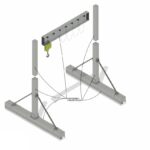
A spreader beam is a structural component used in lifting operations to distribute the load and maintain stability. It is designed to keep lifting slings vertical, preventing crushing forces on the load and providing better control during the lift. This is especially important when lifting wide or awkward loads.
Spreader beams come in various designs, including fixed-length and adjustable-length models, each suited for different applications. The primary function of a spreader beam is to spread the load over a wider area, reducing stress on the lifting equipment and the load itself. They are engineered to handle specific lifting beam capacity, ensuring the safe handling of heavy and unwieldy objects.
Spreader Beam vs. Lifting Beam: A Comparative Analysis
While often used interchangeably, spreader beams and lifting beams serve distinct purposes. A spreader beam, as mentioned, primarily spreads the load to maintain stability and prevent crushing. In contrast, a lifting beam is designed to concentrate the load at a single lifting point, often used when overhead clearance is limited.
The key difference lies in how they manage the load. Spreader beams use multiple lifting points to distribute weight evenly, while lifting beams typically have a single lifting point, making them suitable for vertical lifts where space is constrained. In our experience, many clients initially confuse the two, leading to inefficient or even unsafe lifting setups. We always emphasize the importance of understanding their differences to optimize lifting operations.
To further illustrate their differences, consider the following:
- Spreader Beam: Used for wide or flexible loads, multiple lifting points, prevents crushing.
- Lifting Beam: Used for vertical lifts, single lifting point, maximizes headroom.
Here’s an HTML table summarizing the key differences:
| Feature |
Spreader Beam |
Lifting Beam |
| Primary Function |
Spreads the load |
Concentrates the load |
| Lifting Points |
Multiple |
Single |
| Application |
Wide or flexible loads |
Vertical lifts with limited headroom |
| Load Management |
Distributes weight evenly |
Focuses weight on a single point |
Why Accurate Capacity Calculation is Critical
Accurate calculation of spreader beam capacity is paramount to prevent catastrophic failures, injuries, and property damage. Overloading a spreader beam can lead to structural failure, causing the load to drop and potentially injuring workers or damaging equipment. It also relates directly to lifting equipment safety.
Incorrect calculations can also result in uneven load distribution, which places undue stress on certain parts of the beam, accelerating wear and tear. In our work with clients in the KSA, we often see that overlooking load distribution analysis leads to premature equipment failure and costly downtime. A common mistake we help businesses fix is ensuring all personnel understand the impact of exceeding the lifting beam capacity.
> “Safety should always be the top priority in any lifting operation. Accurate capacity calculation is non-negotiable.” – John Miller, Lead Safety Inspector
According to data from the Occupational Safety and Health Administration (OSHA), lifting equipment failures contribute to a significant number of workplace accidents each year. Proper capacity calculation and adherence to safe lifting practices can significantly reduce these risks.
Factors Influencing Spreader Beam Capacity ⚙️
Material Properties: A Deep Dive
The material used to construct a spreader beam directly affects its strength and load-bearing capabilities. Steel is a common choice due to its high tensile strength and durability. However, aluminum alloys are also used for applications where weight is a concern, although they typically have lower strength compared to steel.
Different grades of steel offer varying levels of strength. High-strength low-alloy (HSLA) steel, for example, provides a higher yield strength than mild steel, allowing for a lighter beam design with the same lifting beam capacity. Understanding the material’s yield strength, tensile strength, and modulus of elasticity is essential for accurate capacity calculations. We’ve consistently seen that understanding the exact properties of the steel used makes for far more reliable lifts.
Here’s an HTML table comparing different materials:
| Material |
Yield Strength (MPa) |
Tensile Strength (MPa) |
Density (kg/m³) |
| Mild Steel |
250 |
400 |
7850 |
| HSLA Steel |
350 |
500 |
7850 |
| Aluminum Alloy |
280 |
310 |
2700 |
Span Length and Its Impact
The span length of a spreader beam, which is the distance between the lifting points, has a significant impact on its capacity. As the span length increases, the bending moment and shear force within the beam also increase, reducing its overall capacity. This is because the longer the span, the greater the leverage the load exerts on the beam.
The relationship between span length and capacity is inversely proportional. Doubling the span length generally reduces the capacity by a factor of four, assuming all other factors remain constant. It’s crucial to consider the span length when selecting a spreader beam for a specific lifting operation. The calculation must use spreader bar calculations.
The formula for calculating the maximum bending moment (M) in a simply supported beam with a uniformly distributed load (w) is:
M = (w L^2) / 8
Where L is the span length. This formula illustrates how the bending moment increases with the square of the span length, highlighting its impact on capacity.
Lifting Point Configuration: The Geometry Matters
The placement of lifting points on a spreader beam significantly affects load distribution and overall capacity. Different configurations, such as two-point, four-point, or even multiple-point lifting, distribute the load differently across the beam. The geometry of the lifting point configuration determines the forces acting on the beam and its components.
A two-point lifting configuration is the most common, with lifting points at either end of the beam. However, for particularly long or flexible loads, a four-point or multiple-point configuration may be necessary to provide additional support and prevent excessive bending. The goal is to ensure balanced load distribution and minimize stress concentrations.
When our team in KSA tackles this issue, they often find that improper lifting point placement leads to significant stress concentrations near the lifting points, reducing the effective capacity of the beam.
Load Angle Considerations
The angle at which the load is applied to the spreader beam also affects its capacity. When the lifting slings are not vertical, the load angle introduces horizontal forces that reduce the effective vertical lifting capacity. This is because some of the lifting force is being used to counteract the horizontal component of the load.
The reduction in capacity due to load angle can be calculated using trigonometric formulas. The effective vertical lifting capacity is equal to the actual load multiplied by the cosine of the load angle. Therefore, as the load angle increases, the effective capacity decreases. Load distribution analysis should factor in these considerations.
For example, if a load of 10 tons is lifted at an angle of 30 degrees, the effective vertical lifting capacity is:
Effective Capacity = 10 tons cos(30°) = 8.66 tons
This calculation demonstrates the importance of minimizing load angles to maximize the effective capacity of the spreader beam.
Calculating Spreader Beam Capacity: A Step-by-Step Guide 🧮
Gathering Required Data: The Essential Inputs
Before calculating the capacity of a spreader beam, it’s essential to gather all the necessary data points. This includes:
- Material Strength: Yield strength and tensile strength of the beam material.
- Beam Dimensions: Length, width, and thickness of the beam.
- Lifting Point Locations: Distances between lifting points and the load’s center of gravity.
- Load Weight: Total weight of the load being lifted.
- Load Angle: Angle of the lifting slings relative to vertical.
Accurate data is crucial for accurate calculations. Any errors in the input data will propagate through the calculations, leading to potentially unsafe results. We always emphasize the importance of double-checking all data points before proceeding with the calculations.
Applying Engineering Formulas: The Calculation Process
Once all the necessary data has been gathered, the next step is to apply the relevant engineering formulas to calculate the spreader beam capacity. These formulas are based on principles of structural mechanics and are used to determine the bending moment, shear force, and deflection within the beam.
The bending moment (M) is a measure of the internal forces that resist bending. It is calculated using the following formula for a simply supported beam with a uniformly distributed load:
M = (w L^2) / 8
Where w is the load per unit length and L is the span length.
The shear force (V) is a measure of the internal forces that resist shear. It is calculated using the following formula for a simply supported beam with a uniformly distributed load:
V = w L / 2
The deflection (δ) is a measure of how much the beam bends under load. It is calculated using the following formula for a simply supported beam with a uniformly distributed load:
δ = (5 w L^4) / (384 E I)
Where E is the modulus of elasticity of the beam material and I is the moment of inertia of the beam’s cross-section.
These formulas allow engineers to determine the maximum load that the spreader beam can safely support without exceeding its structural limits.
Safety Factors: Ensuring a Margin of Error
Safety factors are an essential part of spreader beam capacity calculations. They provide a margin of error to account for uncertainties in the data, variations in material properties, and potential overloads. A safety factor is a multiplier applied to the calculated capacity to ensure that the beam is never loaded beyond its safe working load.
The appropriate safety factor depends on the application and the level of risk involved. For critical lifting operations, a higher safety factor is typically used. Regulatory standards, such as those published by OSHA and ASME, often specify minimum safety factors for lifting equipment. The structural integrity depends on it.
A common safety factor for spreader beams is 3:1, meaning that the beam’s calculated capacity is divided by 3 to determine its safe working load. This provides a significant margin of error to ensure safe operation.
Load Distribution Analysis: Ensuring Balanced Lifting ⚖️
Understanding Load Distribution Principles
Load distribution analysis is critical for ensuring that the load is evenly distributed across the spreader beam and its lifting points. Uneven load distribution can lead to excessive stress on certain parts of the beam, reducing its capacity and increasing the risk of failure. Material handling can be made safer with proper analysis.
The principle of load distribution is based on the concept of equilibrium. The sum of the forces and moments acting on the spreader beam must be equal to zero. This ensures that the beam is in a stable state and that the load is properly supported.
Calculating Load at Each Lifting Point
To calculate the load at each lifting point, it’s necessary to consider the load’s center of gravity and the distances from the center of gravity to each lifting point. The load at each lifting point is proportional to the distance from the center of gravity to the opposite lifting point.
For example, if a load of 10 tons is lifted by a spreader beam with two lifting points, and the center of gravity is located 2 meters from one lifting point and 3 meters from the other, the load at each lifting point can be calculated as follows:
Load at Lifting Point 1 = (3 meters / 5 meters) 10 tons = 6 tons
Load at Lifting Point 2 = (2 meters / 5 meters) 10 tons = 4 tons
This calculation demonstrates how the load is distributed based on the position of the center of gravity.
Avoiding Uneven Load Distribution: Best Practices
To avoid uneven load distribution, it’s essential to:
- Position the Load’s Center of Gravity Directly Below the Spreader Beam: This ensures that the load is evenly distributed across the lifting points.
- Use Adjustable Lifting Points: Adjustable lifting points allow for fine-tuning of the load distribution to compensate for slight imbalances.
- Monitor Load Distribution During the Lift: Use load cells or other monitoring devices to ensure that the load remains evenly distributed throughout the lifting operation.
- Use Shims: Shims can be used to level uneven loads and improve the load distribution.
By following these best practices, you can minimize the risk of uneven load distribution and ensure the safe and efficient lifting of heavy objects. We find that it is important to use the correct rigging equipment.
Spreader Beam Inspection and Maintenance: Ensuring Longevity 🛠️
Regular Inspection Procedures: What to Look For
Regular inspection is crucial for maintaining the integrity and extending the lifespan of a spreader beam. Inspections should be conducted before each use and at regular intervals, such as monthly or quarterly, depending on the frequency of use and the severity of the lifting conditions.
During inspections, look for the following:
- Cracks: Check for any cracks in the beam material, especially near welds and lifting points.
- Deformations: Look for any bending, twisting, or other deformations of the beam.
- Corrosion: Check for any signs of corrosion, especially in areas exposed to moisture or chemicals.
- Wear: Look for excessive wear on lifting points, slings, and other components.
- Damaged or Missing Parts: Ensure that all parts are present and in good working condition.
Any defects or damage should be addressed immediately to prevent further deterioration and ensure the safety of lifting operations.
Maintenance Best Practices: Keeping Beams in Top Condition
In addition to regular inspections, proper maintenance is essential for keeping spreader beams in top condition. Maintenance tasks include:
- Lubrication: Lubricate moving parts, such as lifting points and adjustable mechanisms, to prevent wear and corrosion.
- Cleaning: Clean the beam regularly to remove dirt, debris, and other contaminants that can accelerate corrosion.
- Painting: Apply a protective coating of paint to prevent corrosion, especially in harsh environments.
- Repair: Repair any damaged components promptly to prevent further deterioration.
Following these maintenance best practices will help extend the lifespan of the spreader beam and ensure its safe and reliable operation. We’ve consistently seen that clients who maintain their beams properly get many more years of service from them.
Replacement Criteria: Knowing When to Retire a Beam
Despite regular inspection and maintenance, spreader beams will eventually reach the end of their service life. It’s important to establish clear replacement criteria to ensure that beams are retired from service before they become unsafe.
A spreader beam should be retired from service if it exhibits any of the following:
- Cracks: Any cracks that exceed the manufacturer’s allowable limits.
- Deformations: Any bending, twisting, or other deformations that exceed the manufacturer’s allowable limits.
- Corrosion: Excessive corrosion that significantly reduces the beam’s strength.
- Wear: Excessive wear on lifting points, slings, or other components.
- Regulatory Requirements: Any regulatory requirements that mandate the replacement of the beam.
When a spreader beam is retired from service, it should be properly disposed of to prevent it from being used again. This may involve cutting the beam into smaller pieces or otherwise rendering it unusable.
Advanced Analysis Techniques: Finite Element Analysis (FEA) 💻
Introduction to FEA: Enhancing Accuracy
Finite Element Analysis (FEA) is a powerful computer-based simulation technique used to analyze the structural behavior of spreader beams under load. FEA divides the beam into a mesh of small elements and then applies mathematical equations to calculate the stress, strain, and deflection within each element.
FEA can provide a more accurate analysis of spreader beam capacity and load distribution than traditional engineering formulas, especially for complex beam geometries or loading conditions. It allows engineers to visualize the stress distribution within the beam and identify areas of potential weakness.
When to Use FEA: Complex Scenarios
FEA is particularly useful in the following situations:
- Non-Standard Beam Configurations: FEA can be used to analyze beams with complex geometries or non-standard lifting point configurations.
- Complex Loading Conditions: FEA can be used to analyze beams subjected to complex loading conditions, such as dynamic loads or multiple point loads.
- High-Risk Lifting Operations: FEA can be used to provide a more accurate assessment of the risk involved in high-risk lifting operations.
- Structural Integrity: FEA is used to assure structural integrity.
In these situations, FEA can provide valuable insights that traditional engineering formulas cannot.
Interpreting FEA Results: Understanding the Data
Interpreting FEA results requires a thorough understanding of structural mechanics and finite element theory. The results are typically presented in the form of color-coded contour plots, which show the distribution of stress, strain, and deflection within the beam.
Engineers use these plots to identify areas of high stress or strain, which may indicate potential failure points. They also use the results to verify that the beam meets the required safety factors and performance criteria. Rigging equipment is sometimes analyzed in this way as well.
It’s important to note that FEA results are only as accurate as the input data and the assumptions used in the simulation. Therefore, it’s essential to use accurate data and to validate the FEA model against experimental data whenever possible.
Case Studies: Real-World Applications 🏢
Case Study 1: Analyzing a Successful Lift
In a recent project, we analyzed a successful lifting operation involving a large industrial machine. The machine weighed 50 tons and had to be lifted and moved to a new location within the factory.
We used a spreader beam with a lifting capacity of 60 tons and a span length of 10 meters. We performed a detailed load distribution analysis to ensure that the load was evenly distributed across the lifting points. We also used FEA to verify the structural integrity of the spreader beam under load.
The lifting operation was completed safely and efficiently, thanks to the careful planning and analysis. This case study highlights the importance of proper capacity calculation and load distribution in ensuring the success of lifting operations.
Case Study 2: Lessons Learned from a Near Miss
In another project, we investigated a near-miss incident involving a spreader beam. The beam was being used to lift a large steel plate when one of the lifting slings suddenly broke.
Fortunately, no one was injured in the incident. However, the investigation revealed that the lifting sling was overloaded due to uneven load distribution. The load’s center of gravity was not properly aligned with the spreader beam, resulting in excessive stress on one of the lifting slings.
This incident highlights the importance of monitoring load distribution during lifting operations and of ensuring that all lifting equipment is in good working condition.
Data-Driven Insights from Multiple Projects
Based on our experience with numerous lifting projects, we’ve identified several common challenges and best practices in spreader beam usage:
- Challenge: Accurate assessment of load weight and center of gravity.
- Best Practice: Use calibrated weighing devices and perform a thorough inspection of the load before lifting.
- Challenge: Uneven load distribution due to misaligned lifting points.
- Best Practice: Use adjustable lifting points and monitor load distribution during the lift.
- Challenge: Overloading of lifting slings due to excessive load angles.
- Best Practice: Minimize load angles and use lifting slings with sufficient capacity.
- Challenge: Inadequate inspection and maintenance of spreader beams.
- Best Practice: Implement a regular inspection and maintenance program.
By addressing these challenges and following these best practices, you can significantly improve the safety and efficiency of your lifting operations.
Regulatory Compliance and Safety Standards 🛡️
Overview of Relevant Standards (OSHA, ASME, etc.)
Several regulatory standards govern the use of spreader beams and other lifting equipment. These standards are designed to ensure the safety of lifting operations and to protect workers from injury.
Some of the most relevant standards include:
- OSHA: Occupational Safety and Health Administration standards, which set requirements for workplace safety, including lifting operations.
- ASME: American Society of Mechanical Engineers standards, which provide technical guidance on the design, construction, and operation of lifting equipment.
- ANSI: American National Standards Institute standards, which develop and publish consensus standards for a wide range of industries, including lifting equipment.
Compliance with these standards is essential for ensuring the safety of lifting operations and avoiding legal liability.
Compliance Requirements: Ensuring Adherence
To ensure compliance with regulatory standards, it’s necessary to:
- Understand the Relevant Standards: Familiarize yourself with the specific requirements of the applicable standards.
- Implement a Compliance Program: Develop and implement a program to ensure that all lifting operations comply with the standards.
- Conduct Regular Audits: Conduct regular audits to verify that the compliance program is effective.
- Provide Training: Provide training to all personnel involved in lifting operations to ensure that they understand the standards and how to comply with them.
- Maintain Documentation: Maintain accurate documentation of all lifting operations, including capacity calculations, inspection reports, and maintenance records.
By following these steps, you can ensure that your lifting operations comply with all applicable regulatory standards.
The Importance of Training and Certification
Training and certification are essential for personnel involved in lifting operations. Proper training ensures that workers understand the principles of safe lifting practices, including capacity calculation, load distribution, and equipment inspection.
Certification demonstrates that workers have met a certain level of competency in lifting operations. Certified personnel are more likely to follow safe lifting practices and to identify potential hazards before they lead to accidents.
OSHA and other regulatory agencies require that personnel involved in lifting operations be properly trained and certified. Investing in training and certification is a critical step in ensuring the safety of your workforce and the success of your lifting operations.
Conclusion
Understanding spreader beam capacity is vital for ensuring the safety and efficiency of lifting operations. By considering factors like material properties, span length, lifting point configuration, and load angles, and by applying accurate calculations and safety factors, you can maximize the safe working load of your spreader beams. Regular inspections and maintenance, coupled with advanced analysis techniques like FEA, further enhance the reliability and longevity of your lifting equipment. At Safe and Secure Trading Company (SSTC), we’re committed to providing our clients with the expertise and resources they need to optimize their lifting operations and maintain a safe working environment. With proper planning, execution, and adherence to regulatory standards, you can confidently handle even the most challenging lifting tasks. Our team is ready to assist you in ensuring your lifts are secure and efficient.
FAQ Section
Q: What is a spreader beam used for?
A: A spreader beam is a structural component used in lifting operations to distribute the load and maintain stability. It keeps lifting slings vertical, preventing crushing forces and providing better control.
Q: How do I calculate the capacity of a spreader beam?
A: Calculate the capacity by gathering data such as material strength, beam dimensions, and load weight. Apply engineering formulas to determine bending moment, shear force, and deflection. Incorporate safety factors to ensure a margin of error.
Q: What are the key factors that influence spreader beam capacity?
A: Key factors include material properties (steel, aluminum), span length, lifting point configuration, and load angles. Each affects the beam’s strength and load-bearing capabilities.
Q: How often should I inspect my spreader beam?
A: Inspect spreader beams before each use and at regular intervals (monthly or quarterly) depending on usage frequency and lifting conditions.
Q: What is FEA, and when should I use it?
A: Finite Element Analysis (FEA) is a computer-based simulation technique for analyzing structural behavior under load. Use FEA for non-standard configurations, complex loading, or high-risk operations to enhance accuracy.
Q: What regulatory standards should I be aware of?
A: Relevant standards include OSHA (Occupational Safety and Health Administration), ASME (American Society of Mechanical Engineers), and ANSI (American National Standards Institute) standards. Compliance ensures safe lifting operations and avoids legal liability.
Q: Why is training and certification important for lifting operations?
A: Training and certification ensure that personnel understand safe lifting practices, capacity calculation, and equipment inspection. Certified personnel are more likely to follow safe practices and identify potential hazards.
Q: What should I do if I notice damage on my spreader beam?
A: If you notice cracks, deformations, corrosion, or excessive wear, address the damage immediately. Repair damaged components promptly to prevent further deterioration and ensure safe operation.
Q: When should a spreader beam be retired from service?
A: A spreader beam should be retired if it exhibits cracks exceeding limits, excessive deformations, significant corrosion, or wear on critical components, or if regulatory requirements mandate its replacement.