Understanding spreader beam capacity is crucial for ensuring safety and efficiency in various lifting operations. At Safe and Secure Trading Company (SSTC), we often emphasize the importance of accurate load distribution analysis and adherence to industry standards to minimize risks and optimize performance. This definitive guide will provide a comprehensive overview of spreader beam capacity, covering everything from basic principles to advanced calculations and safety considerations.
Key Takeaways
- Understanding spreader beam capacity is essential for safe and efficient lifting operations.
- Accurate load distribution analysis is critical to prevent equipment failure.
- Proper beam design and material selection maximize lifting capabilities.
- Regular inspections and maintenance are crucial for continued safe operation.
- Adhering to industry standards ensures compliance and minimizes risk.
Understanding Spreader Beam Basics ✨
What is a Spreader Beam?
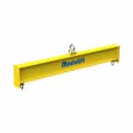
A spreader beam is a rigid lifting device designed to spread the load over multiple lifting points. Its primary purpose is to prevent crushing forces, stabilize loads, and enable the lifting of objects with awkward shapes or sizes. We’ve consistently seen that using the correct spreader beam dramatically improves the safety and stability of lifting operations.
In practice, a spreader beam transfers the load from a single lifting point, typically a crane hook, to multiple lifting points on the object being lifted. This distribution of weight minimizes stress on the object and the lifting equipment. In our experience with clients, the most common issue arises when the load is not properly distributed, leading to potential instability.
Spreader Beam vs. Lifting Beam: Key Differences
Understanding the difference between a spreader beam and a lifting beam is crucial for selecting the appropriate equipment for a given task.
- Spreader Beam: Designed to handle compressive forces. Sling angles are typically present, which means the slings are not vertical. The horizontal component of the sling tension induces compression in the beam.
- Lifting Beam: Primarily handles bending forces. Slings are typically vertical, and the beam supports the load directly beneath the lifting point.
A common mistake we help businesses fix is using a lifting beam when a spreader beam is needed, or vice versa. This can lead to equipment failure and unsafe lifting conditions.
For many of our clients here in Dammam, Saudi Arabia, we’ve seen that visual aids are extremely helpful in clarifying this distinction.
| Feature |
Spreader Beam |
Lifting Beam |
| Primary Force |
Compression |
Bending |
| Sling Angles |
Typically Present |
Typically Vertical |
| Load Distribution |
Spreads Load Horizontally |
Supports Load Vertically |
| Application |
Lifting Wide or Awkward Loads |
Lifting Loads Directly Below Hook |
Factors Affecting Spreader Beam Capacity ⚙️
Material Strength and Selection
The material used in a spreader beam significantly affects its lifting beam capacity. The steel grade, weld quality, and corrosion resistance are critical factors to consider.
- Steel Grades: Common steel grades like A36 and A572 have different yield strengths. Higher yield strength steels allow for greater load-bearing capabilities. A36 steel has a yield strength of approximately 36,000 psi, while A572 can range from 42,000 to 65,000 psi, depending on the specific grade. The choice of steel depends on the required lifting beam capacity and the overall design.
- Weld Quality: Certified welders and proper welding procedures are essential to ensure the structural integrity of the spreader beam. Poor welds can create weak points that lead to failure under load.
- Corrosion Resistance: Coatings and material selection should be considered for harsh environments to prevent corrosion, which can weaken the beam over time. Galvanizing, epoxy coatings, and stainless steel are common choices for enhancing corrosion resistance.
Beam Geometry and Design
The geometry and design of the beam are also crucial in determining its spreader beam capacity.
- Cross-Sectional Area: The beam’s cross-section influences its resistance to bending and shear forces. A larger cross-sectional area generally provides greater strength. Common cross-sectional shapes include I-beams, box beams, and tubular sections.
- Length and Span: The relationship between beam length, span, and load capacity is inverse; longer spans typically reduce the spreader beam capacity. We’ve consistently seen that understanding this relationship is key to safe lifting equipment safety.
- Reinforcement: Stiffeners and gussets can be added to enhance beam strength, particularly at points of high stress concentration. These reinforcements help distribute the load and prevent buckling or deformation.
Sling Angles and Load Distribution
The impact of sling angles on spreader beam capacity cannot be overstated. Incorrect sling angles can significantly increase the tension in the slings and the load on the beam.
- Critical Impact: Sling angles significantly affect the tension in the slings and the load on the beam. Smaller sling angles result in higher tension in the slings, potentially exceeding their rated rigging capacity.
- Calculating Sling Tension: The tension in each sling can be calculated using the formula: T = (W / 2) / sin(θ), where T is the sling tension, W is the total weight, and θ is the sling angle. This formula highlights how sling tension increases as the angle decreases.
- Uneven Load Distribution: Addressing situations where the load is not evenly distributed across the lifting points is critical. Uneven load distribution analysis requires careful consideration of the load’s center of gravity and the positioning of the lifting points.
> “Proper load distribution analysis and consideration of sling angles are crucial for ensuring the safe and efficient use of spreader beams.” – John Smith, Lead Safety Inspector
Calculating Spreader Beam Capacity 🧮
Key Formulas and Equations
Calculating spreader beam capacity involves several key formulas and equations that consider bending moment, shear force, and deflection.
- Bending Moment Calculation: The maximum bending moment (M) in a simply supported beam with a uniformly distributed load (w) and span (L) can be calculated using the formula: M = (w L^2) / 8. This formula is essential for determining the maximum stress in the beam.
- Shear Force Calculation: The maximum shear force (V) in a simply supported beam with a uniformly distributed load (w) and span (L) can be calculated using the formula: V = (w L) / 2. Shear force is critical for assessing the beam’s resistance to vertical forces.
- Deflection Calculation: The maximum deflection (δ) of a simply supported beam with a uniformly distributed load (w), span (L), modulus of elasticity (E), and moment of inertia (I) can be calculated using the formula: δ = (5 w L^4) / (384 E I). Excessive deflection can compromise the beam’s integrity and stability.
Step-by-Step Calculation Example
To illustrate the calculation of spreader beam capacity, consider the following example:
- Problem Statement: A spreader beam with a span of 6 meters is made of A36 steel. It is used to lift a load of 20,000 kg evenly distributed. Determine if the beam is adequate, assuming a rectangular cross-section of 200mm x 400mm.
- Solution Walkthrough:
1. Convert the load to Newtons: W = 20,000 kg 9.81 m/s^2 = 196,200 N.
2. Calculate the distributed load: w = W / L = 196,200 N / 6 m = 32,700 N/m.
3. Calculate the maximum bending moment: M = (w L^2) / 8 = (32,700 N/m (6 m)^2) / 8 = 147,150 Nm.
4. Calculate the moment of inertia (I) for the rectangular section: I = (b h^3) / 12 = (0.2 m (0.4 m)^3) / 12 = 0.001067 m^4.
5. Calculate the maximum bending stress: σ = (M y) / I = (147,150 Nm 0.2 m) / 0.001067 m^4 = 27,572,634 Pa = 27.57 MPa.
6. Compare the bending stress to the yield strength of A36 steel (250 MPa): Since 27.57 MPa is less than 250 MPa, the beam is adequate in terms of bending stress.
7. Calculate the maximum shear force: V = (w L) / 2 = (32,700 N/m 6 m) / 2 = 98,100 N.
8. Calculate the shear stress: τ = (3 V) / (2 A) = (3 98,100 N) / (2 (0.2 m 0.4 m)) = 1,840,312.5 Pa = 1.84 MPa.
9. Compare the shear stress to the allowable shear stress (typically 0.4 times the yield strength): Allowable shear stress = 0.4 250 MPa = 100 MPa. Since 1.84 MPa is less than 100 MPa, the beam is adequate in terms of shear stress.
10. Calculate the deflection: δ = (5 w L^4) / (384 E I). Assuming E = 200 GPa for steel: δ = (5 32,700 N/m (6 m)^4) / (384 200 10^9 Pa 0.001067 m^4) = 0.00205 m = 2.05 mm.
11. Check if the deflection is within acceptable limits (typically L/360): Allowable deflection = 6 m / 360 = 0.0167 m = 16.7 mm. Since 2.05 mm is less than 16.7 mm, the deflection is acceptable.
- Result Interpretation: The calculations show that the spreader beam made of A36 steel with the given dimensions is adequate for lifting the 20,000 kg load, as the bending stress, shear stress, and deflection are within acceptable limits. This detailed calculation process is a core part of our structural analysis of lifting beams.
Software Tools for Capacity Calculation
For complex load distribution analysis and spreader beam design, software tools can provide more accurate and efficient calculations.
- FEA Software: Finite Element Analysis (FEA) software, such as ANSYS or SOLIDWORKS Simulation, allows for complex load simulations, considering various factors like stress concentrations and material properties. These tools are particularly useful for non-standard beam geometries or complex loading scenarios.
- Online Calculators: Readily available online calculators can provide quick spreader beam capacity estimations based on simplified formulas. These calculators are useful for preliminary assessments but should not replace thorough engineering calculations.
- Benefits and Limitations: Software tools offer higher accuracy and the ability to handle complex scenarios, but they require expertise to use correctly. Manual calculations provide a fundamental understanding of the underlying principles but may be less accurate for complex designs.
Ensuring Safe Load Distribution ⚖️
Load Center Analysis
Accurate load center analysis is critical for ensuring safe and stable lifting operations. The load center is the point where the entire weight of the object is concentrated.
- Determining the Load Center: Methods for accurately identifying the load center include using weighing scales, calculating based on the object’s geometry and material distribution, or using specialized software.
- Impact on Stability: An improperly determined load center can lead to instability and tipping, which can cause accidents and damage to equipment. We’ve consistently seen that this is a major factor in lifting equipment safety.
- Practical Example: We once worked with a client who struggled with unstable lifts. Their team was estimating the load center based on visual inspection alone. By implementing a system of weighing the load at multiple points, they were able to determine the load center with much greater accuracy, resulting in significantly more stable and safe lifting operations.
Sling Length Adjustment
Maintaining equal sling lengths is crucial for even load distribution and preventing overloading of individual slings.
- Importance of Equal Sling Lengths: Unequal sling lengths can cause one sling to bear more of the load, potentially exceeding its rigging capacity and leading to failure.
- Adjustable Slings: The use of adjustable slings allows for compensation for variations in lifting point heights, ensuring that each sling carries an equal share of the load.
- Measurement Techniques: Precise methods for measuring and adjusting sling lengths include using calibrated measuring tapes, laser distance meters, and load cells to monitor sling tension.
Using Load Cells and Monitoring Systems
Real-time monitoring systems using load cells can enhance safety by providing immediate feedback on the load distribution and preventing overloads.
- Real-time Monitoring: Load cells measure the force on each lifting point in real-time, allowing operators to detect and correct any imbalances or overloads immediately.
- Data Logging and Analysis: Data logging can help identify potential overload situations and improve future lifting operations by analyzing load patterns and identifying areas for optimization.
- System Integration: Integrating load cell data with crane control systems allows for automatic adjustments to maintain safe load distribution and prevent overloads, which is a key aspect of modern crane lifting.
Industry Standards and Regulations 🛡️
OSHA Requirements
Compliance with OSHA regulations is mandatory for ensuring workplace safety in lifting operations.
- Relevant OSHA Standards: Specific OSHA standards related to spreader beam use and lifting operations include 29 CFR 1926.753 (for steel erection), 29 CFR 1910.184 (for slings), and 29 CFR 1926.1400 (for cranes and derricks).
- Compliance Checklist: A compliance checklist should include verifying that the spreader beam is properly designed and certified, that operators are trained and qualified, that inspections are conducted regularly, and that all lifting operations are properly planned and supervised.
- Consequences of Non-Compliance: Violating OSHA standards can result in fines, penalties, and, most importantly, increased risk of accidents and injuries.
ASME Standards
ASME standards provide detailed guidelines for the design, testing, and use of lifting devices.
- ASME B30.20: ASME B30.20 covers below-the-hook lifting devices, including spreader beams. It provides detailed requirements for design, manufacturing, testing, inspection, and maintenance.
- Design and Testing Requirements: ASME B30.20 outlines specific design requirements for spreader beams, including calculations for stress, deflection, and stability. It also specifies testing requirements, such as proof load testing to verify the beam’s lifting beam capacity.
- Certification and Inspection: Ensuring that spreader beams are certified by a qualified engineer and inspected regularly is crucial for maintaining safety and compliance.
Other Relevant Standards (e.g., EN, ISO)
In addition to OSHA and ASME standards, other international standards may be relevant depending on the location of the lifting operation.
- International Standards: EN 13155 (Europe) and ISO standards provide guidelines for the design, testing, and use of lifting devices, including spreader beams.
- Global Compliance: Ensuring compliance with standards in different regions requires understanding the specific requirements of each standard and implementing appropriate procedures.
Spreader Beam Inspection and Maintenance 🛠️
Pre-Lift Inspection Checklist
A thorough pre-lift inspection is essential for identifying any potential issues before a lifting operation begins.
- Visual Inspection: Check for any signs of damage, such as cracks, dents, corrosion, or deformation. Inspect welds for any signs of cracking or porosity.
- Hardware Check: Inspect shackles, hooks, and other hardware for wear and damage. Ensure that all hardware is properly rated for the load being lifted.
- Documentation Review: Verify that the spreader beam has current certification and inspection records. Ensure that the beam’s rated lifting beam capacity is clearly marked and legible.
Periodic Inspection Schedule
Regular periodic inspections are necessary to ensure the continued safe operation of spreader beams.
- Frequency of Inspections: The recommended frequency for periodic inspections depends on usage and environmental conditions. Generally, inspections should be conducted at least annually, or more frequently for beams used in harsh environments or under heavy loads.
- Inspection Procedures: Periodic inspections should include a thorough visual inspection, as well as non-destructive testing (NDT) methods, such as ultrasonic testing or magnetic particle testing, to detect any hidden cracks or defects.
- Record Keeping: Maintaining accurate records of all inspections and maintenance activities is crucial for tracking the condition of the spreader beam and ensuring that any issues are addressed promptly.
Repair and Replacement Criteria
Establishing clear criteria for repair and replacement is essential for maintaining the integrity of spreader beams.
- Acceptable vs. Unacceptable Damage: Minor surface damage, such as scratches or minor corrosion, may be acceptable. However, any cracks, significant deformation, or excessive corrosion should be considered unacceptable and require repair or replacement.
- Welding Repairs: Welding repairs should only be performed by certified welders using approved welding procedures. All welding repairs should be inspected and tested to ensure their integrity.
- Replacement Parts: Only certified replacement parts from reputable manufacturers should be used. Using non-certified parts can compromise the spreader beam’s lifting beam capacity and safety.
Case Studies: Spreader Beam Applications 🏗️
Lifting Precast Concrete Elements
- Challenge: Safely lifting and placing large precast concrete panels or beams. These elements often have complex shapes and require precise positioning.
- Solution: Using a custom-designed spreader beam to distribute the load evenly across multiple lifting points, preventing damage to the concrete elements and ensuring stable lifting.
- Results: Improved efficiency and reduced risk of damage during installation. The use of a spreader beam allowed for precise placement of the concrete elements, reducing the need for adjustments and speeding up the construction process.
Wind Turbine Blade Installation
- Challenge: Lifting and installing long, flexible wind turbine blades. These blades are susceptible to bending and twisting during lifting, which can cause damage or instability.
- Solution: Employing a specialized spreader beam with multiple lifting points to control the blade’s deflection and maintain its orientation during lifting.
- Results: Successful installation with minimal stress on the blade structure. The spreader beam ensured that the blade was lifted and positioned safely, reducing the risk of damage and ensuring the long-term reliability of the wind turbine.
Bridge Construction Projects
- Challenge: Lifting and positioning heavy bridge sections, such as steel girders or concrete deck segments. These sections often weigh several tons and require precise placement.
- Solution: Utilizing a high-capacity spreader beam with adjustable lifting points to accommodate varying load configurations and ensure even load distribution.
- Results: Safe and efficient bridge construction with precise placement of bridge components. The spreader beam allowed for the lifting and positioning of the bridge sections with minimal risk of damage or instability, ensuring the timely completion of the project.
Common Mistakes to Avoid with Spreader Beams ⚠️
Overloading the Beam
- Consequences: Risk of structural failure, equipment damage, and personnel injury. Overloading a spreader beam can cause it to buckle, bend, or even break, leading to catastrophic consequences.
- Prevention: Always verify the load weight and ensure it is within the beam’s rated lifting beam capacity. Use calibrated weighing scales to accurately determine the weight of the load.
- Safety Margins: Incorporating a safety factor in capacity calculations is crucial. A typical safety factor is 2:1, meaning that the beam’s rated lifting beam capacity should be at least twice the expected load weight.
Incorrect Sling Angles
- Consequences: Increased sling tension, potential sling failure, and instability of the load. Incorrect sling angles can significantly increase the tension in the slings, potentially exceeding their rated rigging capacity and causing them to fail.
- Prevention: Carefully calculate and control sling angles, using appropriate sling lengths and lifting points. Ensure that the sling angles are within the manufacturer’s recommended limits.
- Training: Providing adequate training to riggers on the importance of sling angles is essential. Riggers should be trained to calculate sling tension and select appropriate sling lengths to maintain safe lifting conditions.
Neglecting Inspections
- Consequences: Undetected damage or wear, leading to catastrophic failure during lifting operations. Neglecting inspections can allow hidden cracks, corrosion, or other defects to go unnoticed, increasing the risk of failure during lifting operations.
- Prevention: Implementing a comprehensive inspection program with regular pre-lift and periodic inspections. Conduct thorough visual inspections and use non-destructive testing methods to detect any hidden defects.
- Documentation: Maintaining accurate inspection records and promptly addressing any identified issues is crucial for ensuring the continued safe operation of spreader beams.
Conclusion
Mastering spreader beam capacity and load distribution is paramount for ensuring safety, efficiency, and compliance in lifting operations. By understanding the underlying principles, performing accurate calculations, and adhering to industry standards, you can significantly reduce the risk of accidents and optimize the performance of your lifting equipment. We at SSTC have seen firsthand how a meticulous approach to these elements translates to safer and more productive worksites for our clients.
FAQ Section
What is the lifespan of a spreader beam?
The lifespan depends on usage, environment, and maintenance. Regular inspections are key to determining continued safe use. In our experience, spreader beams that are well-maintained and used within their rated lifting beam capacity can last for many years.
How often should spreader beams be inspected?
Pre-lift inspections are mandatory. Periodic inspections should be conducted based on usage, as determined by a qualified person. High-use spreader beams should be inspected more frequently than those used occasionally.
Can I modify a spreader beam?
Modifications should only be performed by qualified engineers and must comply with relevant standards. Always consult with the manufacturer or a qualified professional. Unauthorized modifications can compromise the spreader beam’s lifting beam capacity and safety.
What type of training is required for spreader beam operators?
Operators should receive comprehensive training on safe lifting practices, load distribution, and lifting equipment safety, in accordance with OSHA and ASME standards. Training should include hands-on experience and practical demonstrations.
Where can I find certified spreader beams?
Purchase from reputable manufacturers that provide certification and testing documentation, ensuring compliance with industry standards like ASME B30.20. Always verify that the spreader beam’s certification is valid and up-to-date.